Mark,
Yes we have designed with ALL ESS IC's (from the very first silicon - which IIRC was the 9006/9008) including the latest "mobile phone" orientated devices (with internal MQA renders).
ASRC can be bypassed in all devices + volume control* - this does not change the fact that DSD input is remodulated before it hits the DAC array.
* Later devices go further, not only can certain sections be bypassed, but they are also powered down to save energy - every mW is important for the Mobile phone industry.
Our DAC designs for Project use the ES9038Q2M in Dual mono operation...
Our DAC designs for Project use the ES9038Q2M in Dual mono operation...
Interesting. On the surface that would appear to lower noise a little and improve stereo separation. Any other benefits?
IMO, operating in Dual mono is more about separating "second order" effects - what I mean by this is the effect of Data modulation on the PSU / Clock etc. on the DAC substrate.
IME, the improvement in SQ is rather more then the small improvement in S/N.
Tricks are required to keep the ES9038Q2M's in Phase Sync due to the operation of the ASRC.... Its ALWAYS better if possible to operate the DAC with ASRC bypassed (such as afforded by correct USB Async. implementation).
IME, the improvement in SQ is rather more then the small improvement in S/N.
Tricks are required to keep the ES9038Q2M's in Phase Sync due to the operation of the ASRC.... Its ALWAYS better if possible to operate the DAC with ASRC bypassed (such as afforded by correct USB Async. implementation).
Always nice to talk to you, John. If you are ever out our way in your worldly travels (Auburn, CA), please stop by for a visit. We have a exceptional and friendly high end analog audio designer, Jam, who I am sure would also enjoy hanging out for an afternoon (or whatever time works).
I own S2 digital, but I have to say it is the least DAC/HPA I listen nowadays. I suspect SABRE9602 output stage might be somehow responsible for this. taking advantage that JohnW is here, I would like to ask was there any SQ related reasons for selecting SABRE9602?
I own S2 digital, but I have to say it is the least DAC/HPA I listen nowadays. I suspect SABRE9602 output stage might be somehow responsible for this. taking advantage that JohnW is here, I would like to ask was there any SQ related reasons for selecting SABRE9602?
No not, really its about the available PCB space (the size of the ProJect DAC encloses is always a battle), PSU requirements (it generates the negative PSU rail so no output coupling capacitors are required) + there is only so much you can do on cost grounds with a product that is manufactured in Europe. European BOM pricing is simply off the scale compared to what I'm used to with production cost in Asia from an decent manufacturer.
People are understandably against "Made in China" - while the QC of European manufactured goods is nearly always high - we understand what we are doing / designing, you have such a negative impact due to the crazy high component costs etc..
Its very hard to compete on cost terms... a Chinese made unit (European designed) can just have so much more for the same cost 🙁 you just need to insure constant quality which in my experience is near impossible without 100% oversight, and WHO wants to live on a production line in China... I've done that for 25 years of my life!!! - no MORE!!! ...
Its not easy to have your cake and eat it...
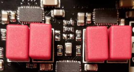
To improve your DAC's sound, I suggest replacing the x2 470pF Wima caps above each DAC (so x4 caps in total) with 1000uF 4V or 6.3V Organic / OsCon type Caps... The Negative terminal of the Cap to Ground (Probe the Ground terminal position with a Multimeter). This opens up the sound stage + deeper Bass etc....
During the ProJect DAC development, we bypassed the SABRE9602 output stage with a fancy fully balanced Mosfet Class A discrete I/V output stage with Bulk foil resistors, Polystyrene capacitors etc. but more improvement was brought by improvements to the PSU - even a decent clean DC input to the DAC makes a big difference.
Dropbox - DAC lash up.JPG
Above:- Class A Mosfet Fully balanced I/V OPS hooked upto the ProJect DAC (early version design based on the ES9028Q2M - not the later 9038Q2M's used in production)... During listening tests we found that PSU improvements made a bigger difference... OPS is not "So" bad....
I must say that we have grown to REALLY dislike the ESS sound signature - and prefer the more natural / "Real sounding" AKM sound... AKM's not perfect, but its far more listenable / preferable to the ESS sound IMO...
With its MQA decoding, Discrete Clock and dual ESS etc, the Little ProJect DAC makes a great platform for DiY upgrades... Just working on such a small unit / SMD is a limting "DiY" factor
Last edited:
Always nice to talk to you, John. If you are ever out our way in your worldly travels (Auburn, CA), please stop by for a visit. We have a exceptional and friendly high end analog audio designer, Jam, who I am sure would also enjoy hanging out for an afternoon (or whatever time works).
Mark,
Be great to meet you guys sometime, however since 9/11 I've really limited my travels to the US as the Airport security / immigration experience is just so unpleasant - I just have a rebellious side that says I'm not going to allow myself to be treated so badly by anyone if I have the choice!!!
Shame really, as I have many fond experiences of working with US company's...
I feel more unwelcome entering the US, then I do say traveling to China... and China is REALLY Grim....
For many years now, the Munich HiFI show has replace the CES as the "Yearly" HiFi industry meet up - if your ever over for the Munich show, it be a great chance to meet. Munich is far bigger / relevant for the HiFi industry then CES ever was...
They do say that the RMAF is decent on the US side 🙂 - sadly never been...
...
To improve your DAC's sound, I suggest replacing the x2 470pF Wima caps above each DAC (so x4 caps in total) with 1000uF 4V or 6.3V Organic / OsCon type Caps... The Negative terminal of the Cap to Ground (Probe the Ground terminal position with a Multimeter). This opens up the sound stage + deeper Bass etc....
...
Thanks a lot John! this is really helpful and very much in line with findings done earlier in this thread. I was hesitating to go for deep S2 digital mods because of so nice enclosure and colour display 🙂
Just to make sure, are you referring to the caps in the pic attached? Are those for ES9311 voltage reference?
Attachments
Thanks a lot John! this is really helpful and very much in line with findings done earlier in this thread. I was hesitating to go for deep S2 digital mods because of so nice enclosure and colour display 🙂
Just to make sure, are you referring to the caps in the pic attached? Are those for ES9311 voltage reference?
Yep, those are the caps.
There are two trains of thought:-
1. The PSU impedance seen by the DAC array across the audio B/W is determined by active circuitry (A regulator with feedback). So the impedance (at any particular frequency point) is determined by the Closed loop gain of the regulator (assuming the feedback is correctly sensing the point of load). Once the regulators Gain has dropped to zero, then the idea is for a capacitor to "cleanly" take over....
So the general idea is to have fixed and constant impedance determined by active circuitry across the audio B/W, followed by RF decoupling / filtering determined by capacitors higher up, outside the audio B/W (no regulator can be fast enough at HF / RF frequency).
This is the approach taken with the S2 design - the premise is that the audio quality is not effected by the sound of the PSU decoupling capacitors... (Note I said "premise" - not reality IMHO)...
The second option is to just "slug" the output of the regulator with mass bulk caps. so these bulk caps dominate the regulators output impedance / loop response (or lack off) across most of the Audio B/W... If the total amount of bulk Capacitance is made so large then the regulator cannot oscillate as its unable to "Move" its output fast enough in face of the low impedance presented by these Bulk caps... its output is "Slugged"... Crude, but in realty the most common method of regulator loop control.
The trouble with this method is that the capacitor is very much in the signal path and secondly, the regulator loop dynamics are effected by the Bulk capacitors value & ESR which is highly temperature dependent (operating on a "chemical" process) - hence the warm up period noticed / required by HiFi equipment...
Its now a designers choice between the sound quality of Active circuitry (Option 1) verses passive circuity (Option 2) - Passive is normally the best option, but the quality of bulk capacitors is so far from perfect and thus really has a Huge impact on SQ...
I'm leaning towards option 2, although the warm up requirement is very noticeable (and the trouble of never finding the perfect "Balanced" sounding capacitor) + it smacks of a crude design... but Hey Ho... this is Audio...!
The capacitor location indicated are the OUTPUT of the AVDD regulator - decoupling the CRITICAL ESS DAC Array...
Swapping the 470pF Film caps (Option 1 operation) to larger 1000uF Bulk caps (Option 2 operation)....
Last edited:
John,
It seems that in the, hey, this is audio field, it may also turn out that regulators as applied to certain types of audio circuits have their own sound aside from the usual things like output impedance we tend to think of. It has been suggested a factor is regulator linearity, presumably largely that of the error amplifier circuitry.
It seems that in the, hey, this is audio field, it may also turn out that regulators as applied to certain types of audio circuits have their own sound aside from the usual things like output impedance we tend to think of. It has been suggested a factor is regulator linearity, presumably largely that of the error amplifier circuitry.
Last edited:
John,
Beautiful. You are a joy to read. And very much agreeable.
Now the question is: what active regulation scenes could compete with a bulky Elna Cerafine cap..
Presently I would vote quite much for locally applied, film decoupled (10uF) lt3042..
Ciao, George
Beautiful. You are a joy to read. And very much agreeable.
Now the question is: what active regulation scenes could compete with a bulky Elna Cerafine cap..
Presently I would vote quite much for locally applied, film decoupled (10uF) lt3042..
Ciao, George
Last edited:
.....
Swapping the 470pF Film caps (Option 1 operation) to larger 1000uF Bulk caps (Option 2 operation)....
thanks for the explanation! however it appears to me that polcap impedance is significantly rising below 100Hz. anyway, so far the best sonical results for both ESS and AKM reference voltages I have been able to achieve with shunt regs described:
S-Audio.Systems // "Nazar`s regulator", variants
John,
Beautiful. You are a joy to read. And very much agreeable.
Now the question is: what active regulation scenes could compete with a bulky Elna Cerafine cap..
Presently I would vote quite much for locally applied, film decoupled (10uF) lt3042..
Ciao, George
George 🙂
Great to catch up with you again after all these years 🙂 I still have your PCM2704 DAC PCB around here somewhere (pretty sure it was your PCB 🙂 )...
I rarely use IC regulators in the audio path thesedays... being impossible to optimise the loop response...
I use a HP 3577A (with LCD upgrade), these are perfect for loop response analyses 🙂 good to be able to confirm simulation results!
Its surprising how bad MOST LDO's wrt PSU rejection are, not to mention output impedance etc. - they typically have very poor loop gain...
Worst case I use a 5534 as "gain block", followed by some form of OPS.. 5534 are cheap as chips (no pun intended 😉 ) and very hard to beat for low noise and "gain" / PSRR...
Where space allows I just go fully discrete - its cheaper and you can optimise the loop gain etc...
Youare correct about the space issue - the ES9311 was developed for mobile phones etc where a bulk cap to decouple the array ids impossible - even if active regulation does not work as well in this application (the ESS DAC array has demanding LF and RF PSU requirements)...
John,
It seems that in the, hey, this is audio field, it may also turn out that regulators as applied to certain types of audio circuits have their own sound aside from the usual things like output impedance we tend to think of. It has been suggested a factor is regulator linearity, presumably largely that of the error amplifier circuitry.
In audio engineering everything appears to be audible - despite so many seeming to make it there life mission to tell us otherwise! 🙁
thanks for the explanation! however it appears to me that polcap impedance is significantly rising below 100Hz. anyway, so far the best sonical results for both ESS and AKM reference voltages I have been able to achieve with shunt regs described:
S-Audio.Systems // "Nazar`s regulator", variants
Well the LF impedance "corner" is determined by the capacitance value 🙂 the regulator will take over output impedance at lower frequency.
Yes, shunt regulators never fail to impress in such applications 🙂 shame about there "Class A" power dissipation which limits there use in our "Green world"!
As designers, we are now being hounded for low operating currents by the EU etc...
a while ago I was trying to build a reg similar to the one below. I guess it should be pretty familiar to you. nevertheless it was prone to oscillations unless putting some 1-2 ohm resistor between output transistor and a couple of 1000uF low ESR caps. perhaps too little capacitance then?
Attachments
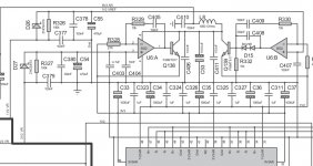
Yes the circuit needs to be optimized to account for the parasites include the ESR of the Caps. used etc. optimization with R392 / C405.. The values reflected on the schematic might not be production PCB values as I tend to scramble circuits to confuse those who copy designs 😀
🙂 Very well put! There are 2 key words (emphasized by me). Those who read it hastily can miss the point.In audio engineering everything appears to be audible - despite so many seeming to make it there life mission to tell us otherwise! 🙁
- Home
- Source & Line
- Digital Line Level
- ES9038Q2M Board