Which AK4137 board do you have?
EDIT: Whichever board, you need DSD_ON, and some combination of F0-F3 (the F outputs are not isolated on I2SoverUSB, and you would need F1 and F2 from it IIRC). Which F pins they would be on the AK4137 board I'm not sure. Depends how they are counting. Depending on which board there we can probably be more specific about the interconnections.
The issue is that AK4137 does not auto detect the incoming I2S format. That includes bit-depth, but I2SoverUSB is always 32-bit (at least as I have the B1-B3 jumpers installed).
Reason I have B1-B3 installed is that although JLSounds is bit cryptic about what the B jumpers do, the configuration I use selects using their clocks, simultaneously outputs both 22/24MHz and 45/49MHz clocks on different pins, and always outputs 32-bit I2S.
Last edited:
Which AK4137 board do you have?
EDIT: Whichever board, you need DSD_ON, and some combination of F0-F3 (the F outputs are not isolated on I2SoverUSB, and you would need F1 and F2 from it IIRC). Which F pins they would be on the AK4137 board I'm not sure. Depends how they are counting. Depending on which board there we can probably be more specific about the interconnections.
The issue is that AK4137 does not auto detect the incoming I2S format. That includes bit-depth, but I2SoverUSB is always 32-bit (at least as I have the B1-B3 jumpers installed).
Reason I have B1-B3 installed is that although JLSounds is bit cryptic about what the B jumpers do, the configuration I use selects using their clocks, simultaneously outputs both 22/24MHz and 45/49MHz clocks on different pins, and always outputs 32-bit I2S.
Hi Mark,
I've got the blue SMP with the smaller OLED display.
Now that makes sense, I'm getting all PCM frequencies being recognised but no DSD, I was reading the I2SoverUSB manual and using the datasheet for the AK4137 noticed that F0-F3 (F1 & F2 hold the DSD 64/128/256 bits) 'sort of match' the A0-A3.
Time to solder on the H1 header and connect some more wires.
Thanks again Mark!
The SMP AK4137 boards use the Amanero pinout pattern for I2S input. The pinout is described in the document at: https://www.amanero.com/drivers/combo384-D.pdf
You are very welcome, of course! 🙂
You are very welcome, of course! 🙂
Last edited:
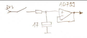
What do you guys think of a supercap as reference for an ad797 AVCC supply.
let's say 1F, charged at startup to 3v3 via a small resistor and the having the supply switched off after a few seconds by a relay. Shouldn't this be the most quiet voltage reference for the input of the ad797?
let's say 1F, charged at startup to 3v3 via a small resistor and the having the supply switched off after a few seconds by a relay. Shouldn't this be the most quiet voltage reference for the input of the ad797?
...Shouldn't this be the most quiet voltage reference for the input of the ad797?
I wouldn't imagine so, since most super caps have ESR and ESL as frequency goes up. They may need bypassing at some audio frequencies. Besides, LT3042 or LT6655 are way quiet enough. If you want you could put a super cap on their input power supply, but they may regulate better with more than 5v input. 7v or 8v input to the reference might be better.
These dacs are hard enough to get working their best, and they seem to perform best with separate regulators for things that need it, with each regulator tailored to best serve the needs of the load. Layout matters a lot too. Ground planes and short connections for sensitive signals are good in most cases. A lot of care should be put into those types of things.
The only sensitive signals that are especially tricky are the dac output connections to the I/V inputs and the ground plane continuity between dac chip and I/V opamps. Reason dac outputs are tricky is that they have some low level RF/HF and tend to cause small but unpleasant distortion in the I/V opamps. I used twisted wires running against the ground plane for a few inches for each dac channel's +- outputs before going into the I/V opamps (which was described earlier in this thread). Other people are continuing to make progress in that area but their solutions are proprietary so far as I know.
Anyway, the point is that super caps are not needed to get the best out of the dac chip, but they seem to help in the case of some implementations. There are many other things that always matter, so I would suggest to go for those first and after the dac is running the best it can using established methods, then that might be an appropriate time to experiment around with super caps if they can improve sound quality. Unfortunately, many people confuse different for better when listening. Listen comparisons should be performed with/without mods several times and over different days to make sure a change is really a change for the better. If the experimenter knows other people that are skilled at listening to very small details for better sound quality, it can be helpful in some cases to get their opinions where listening is done first before they know anything about what the mod involves (don't want them to be biased by excitement over some mod they think is good before listening).
An easy way to judge distortion in A/B listening comparisons is to focus attentions on the sound of vocals on a very cleanly recorded CD. When vocal harmonies are sung, be it a duet or a choral piece, one can hear the IMD that blurs the vocals together instead of sounding like distinct individual voices. There is much more that could be said, but I have talked more than enough already 🙂
Last edited:
I think you might have misunderstood what I mean, so here's a pic to hopefully clarify things...
Regarding ESL and ESR in my depicted use case, would these really matter as the supercap only supplies dc to the very high impedance positive input of the opamp?
Nevertheless you're probably right that the LT3042 is low noise enough, this was just a thought experiment. Still it was interesting enough to make me ask here 🙂 And I'm still interested in your opinion... Btw. If used in a real circuit I'd probably add a yeat another 10k/100n RC lowpass between the supercap and the ad797 with the 100n cap very close to the ad797...
Attachments
The SMP AK4137 boards use the Amanero pinout pattern for I2S input. The pinout is described in the document at: https://www.amanero.com/drivers/combo384-D.pdf
You are very welcome, of course! 🙂
I've been playing and I still can't get a DSD lock. I get a momentary flash (sometimes 0.5 sec) and a slight burst of music then the lock drops.
I'm using the mute and dsd pins on the H1 and have been trying to force DSD64 (using A2 connected to F1).
Any thoughts?
Depending on the value of the super and the value of the resistor it could take a long time for the cap to charge up. An estimate could be make by multiplying the values (in units of ohms and farads) to get the RC time constant. Time to charge up would around 3 - 5 times that.
In addition, due to unspecified levels of ESR/ESL/Dielectric-Absorption verses frequency, a super cap may be ineffective at filtering high frequencies that could adversely affect the sound of your audio. You could try to put a film cap or something in parallel with the supercap. The risk RF/HF on your 3.3v input voltage would depend on things like if it is a dedicated reference or a 3.3v bus shared by other devices. Layout of wiring could also affect RF/HF noise pickup.
On the other hand, putting a supercap there probably wouldn't hurt anything, and there is always some chance it could do some good. You could put a jumper or switch to disconnect the super cap and or to switch to a conventional 10k-ohm/10uf electrolytic filter as recommended by ESS, so as to allow a way to perform listening comparison tests.
As far as what works well from a schematic point of view, the opamp AVCC circuit recommended in post #3003 of this thread works well.
Maybe I should say that it is possible to use supercaps to improve measurements, but the resulting sound quality is not always better, although it can be.
If you want to make design choices you have to decide how to evaluate what choice you think is best. Just doing some mod and not checking to see if measurements or careful listening tests change in the desired direction tends to lead to a mismash of good and band changes, often mostly bad the more that standard proven methods are deviated from.
Many people add super caps to circuits and say they find it takes a few days to a few weeks for sound quality to burn in. Until then they often say the sound is worse. Only way to tell if the cap is burning in or if the listener's ears/brain-processing is burning in is to wait for the burn in time to elapse, the perform A/B tests with/without the mod to make sure of what really happened.
Thanks very much MarkW, your input is very much appreciated!
We just had a discussion here (in fact the whole afternoon and still going) and the supercap option is probably off the table by now. 😉
regarding post #3003, yet another question. I just looked at the datasheet for the LME49720... What makes this opamp especially desirable in this position? Other opamps like the OPA1612 seem to have better specs (let alone the AD797). What should I look out for in this case?
I've been playing and I still can't get a DSD lock. I get a momentary flash (sometimes 0.5 sec) and a slight burst of music then the lock drops.
I'm using the mute and dsd pins on the H1 and have been trying to force DSD64 (using A2 connected to F1).
Any thoughts?
The DSD_ON from the USB board is what tells the AK4137 board MCU to configure the board for DSD input.
Standard DSD64 uses an approximately 2.8MHz clock frequency, roughly the same as the bit-clock frequency for 44.1kHz PCM. I2SoverUSB sets all A1-A3 to zero for that sample rate (see table at bottom of page 11 in the USB board manual). In addition, there an un-isolated signal on H1 called DSD_PCM. There is also an isolated version of that signal on H3 called DSD_PCM_iso. Both of those are the same signal as DSD_ON.
Moving along to the AK4137 board, it looks like Amanero sets F0 to 1 for 44.1kHz. Presumably, it would the same for DSD64. Not sure what the standard for XMOS USB boards is, but may be more like what I2SoverUSB uses. One possibility would be to see if the AK4137 board you have is expecting Amanero or XMOS format signals. If you hold down the selection button on the AK4137 board as it is powered on, it will enter a special configuration mode. In that mode you may set it to Amanero or XMOS. It may be that one or the other setting works better with your hardware combination.
Hopefully some of the above will be helpful. If not, digging deeper into the problem is possible
One other thing though: It is not usually a good idea to start with DSD source material and upsample it to higher sample rate DSD. The problem is that it has to be converted to PCM to resample it to the higher rate. Then it has to be re-modulated back into DSD. Sound quality usually suffers as a result, and in that regard AK4137 specs are not stellar. Probably better to only upsample PCM to DSD, and just bypass resampling for native DSD source material.
Last edited:
...What makes this opamp especially desirable in this position? Other opamps like the OPA1612 seem to have better specs (let alone the AD797). What should I look out for in this case?
Actually, LME49720 is still a great opamp (same as a 4562, and the HV version is LME49860). Problem with them is sensitivity to picking RF and turning it into distortion. Wireless phone base stations withing 10 feet or so will show a whole bunch of FFT spurs. If the circuit is properly shielded in box (steel case is ideal, very lossy at RF), and if I/O interconnections to the box are filtered, then those opamps are still a very good choice for many super low distortion designs.
When boards are operated in less protected RF environments then OPA1612 is a better choice, IME. It could be a fine choice in a box too 🙂
AD797 is kind of special, IMHO, in that it is expensive, still offers exceptional performance and sound quality. However, it can have an issue with stability at the power pins related to capacitance from the rails to ground (see data sheet application section for bypassing). If that isn't a issue in one's application, it can make an excellent AVCC buffer. Of course, its not a dual, so about $20 worth of opamps there when one OPA1612 sounds at most only very slightly different for ES9038Q2M AVCC.
Last ES9038Q2M dac I did used OPA1612 for AVCC. No complaints here.
All the foregoing IMHO, of course! 🙂
Last edited:
The DSD_ON from the USB board is what tells the AK4137 board MCU to configure the board for DSD input.
Standard DSD64 uses an approximately 2.8MHz clock frequency, roughly the same as the bit-clock frequency for 44.1kHz PCM. I2SoverUSB sets all A1-A3 to zero for that sample rate (see table at bottom of page 11 in the USB board manual). In addition, there an un-isolated signal on H1 called DSD_PCM. There is also an isolated version of that signal on H3 called DSD_PCM_iso. Both of those are the same signal as DSD_ON.
Moving along to the AK4137 board, it looks like Amanero sets F0 to 1 for 44.1kHz. Presumably, it would the same for DSD64. Not sure what the standard for XMOS USB boards is, but may be more like what I2SoverUSB uses. One possibility would be to see if the AK4137 board you have is expecting Amanero or XMOS format signals. If you hold down the selection button on the AK4137 as it is powered on, it will enter a special configuration mode. In that mode you may set it to Amanero or XMOS. It may be that one or the other setting works better with your hardware combination.
Hopefully some of the above will be helpful. If not, digging deeper into the problem is possible
One other thing though: It is not usually a good idea to start with DSD source material and upsample it to higher sample rate DSD. The problem is that it has to be converted to PCM to resample it to the higher rate. Then it has to be re-modulated back into DSD. Sound quality usually suffers as a result, and in that regard AK4137 specs are not stellar. Probably better to only upsample PCM to DSD, and just bypass resampling for native DSD source material.
Mark, I'm using this version the I2SoverUSB http://jlsounds.com/uploads/I2SoverUSB v.III.pdf
Definitely agree with you on the DSD source material, just needed to ensure I could use (prove) DSD if needed. 99.99999% of my source material is PCM so I'm not too concerned that if the worst comes to the worst and I can't use DSD. Having Roon just makes it very easy, perhaps far too easy to upsample to anything!!!!
Did you find any option to bypass SRC on DSD, I've read elsewhere that AK4137 to AK DAC connectivity have that feature, although these boards don't have it easily accessible (or at all).
I've set the board to XMOS, definitely worth checking if Amanero changes anything.....I'll let you know when I have a further play.
Good find on the SRC bypass mode, don't recall the Chinese AK4137 boards supporting it though.
As it is a serial control mode option, it might be possible to activate it and access the needed pins.
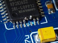
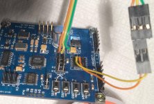
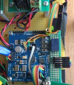
Did that once (for a different reason) with a Chinese AK4137 board. Doubt anyone else would want to go the trouble and risk ruining the board. Pics below. Had to lift MCU pins to take over I2C bus at the right time. Used relay attached to AK board to switch I2C bus control and an external Arudino.
Attachments
Looks fairly easy to me but I work with smaller stuff daily. There is always the option of designing a bespoke test board. PCBs are relatively inexpensive these days.
Yes, a better and more readily controllable AK4137 board could be made for sure. That may happen over in the AK4499 board project thread before too long. Maybe 🙂
In the meantime it would be great if someone wanted to do one for general use. Working on other things myself in the hobby time available.
In the meantime it would be great if someone wanted to do one for general use. Working on other things myself in the hobby time available.
You left out an important step in setting up A/B listening, the level match. Why not explain how to do that to Tfive so that he doesn't waste time doing level unmatched A/B listening.An easy way to judge distortion in A/B listening comparisons is to focus attentions on the sound of vocals on a very cleanly recorded CD.
Good find on the SRC bypass mode, don't recall the Chinese AK4137 boards supporting it though.
Sorry, not been following the thread, so maybe my reply is out of context, but as far as I'm aware, you have to use the ASRC mode if you use the AK4137 as a PCM to PDM (DSD) modulator.
A repeated design weakness with AKM designs is that they dont seem to Round and Dither when they internally truncate internal data paths - so you will see THD components at lower signal levels popping up from the noise floor 🙁
That said, listening to the AK4137 PDM modulator at 256 operation and it sounds better then any of the HQPlayer software modulator / filter options (if PCM to PDM (DSD) is required).
Its just a shame that the AKM designers seem to lack the understanding of why correct interstate Rounding / Dithering (or noise shaping) is so important.
- Home
- Source & Line
- Digital Line Level
- ES9038Q2M Board