Why do you use A-weighting for THD measurements?
My H2 is around -127 and H3 around -108. No compensation. Read from the FFT spectrum.
The H5, H7 and H9 (actually all the way up to H27) are higher than the H2.
My H2 is around -127 and H3 around -108. No compensation. Read from the FFT spectrum.
The H5, H7 and H9 (actually all the way up to H27) are higher than the H2.
We are still doing THD+N testing (and we always use a weighted) and I can see harmonics in the same report.
Now we are starting FFT testing (unweighted)
Before compensation we were at about -114 on the H3.
Now we are starting FFT testing (unweighted)
Before compensation we were at about -114 on the H3.
Last edited:
CDS, did you use the same board? Wonder how you access these registers. Through I2S?
Here two snapshots:

The one above with 0R between DAC and IV;
The one below with 4R7 in between:

Not at all a small difference.
A real challenge with this board would be to get the noise down
Here two snapshots:
The one above with 0R between DAC and IV;
The one below with 4R7 in between:
Not at all a small difference.
A real challenge with this board would be to get the noise down
Wonder how you access these registers. Through I2S?
There is a lot of information of possible interest at Dimdim's website, especially if you look around a bit. If you understand Arduino Code, you might look here: TFT HiFiDuino Pro Project | Dimdim's Blog
You need i2c to control the thd compensation. Basically you need to measure the H2 / H3 and change settings in a register while monitoring for improvements .
Attached is what I got today as far as harmonics. In the next days we will see how to improve further .View attachment harmonics.pdf
1Khz 0dbfs
Attached is what I got today as far as harmonics. In the next days we will see how to improve further .View attachment harmonics.pdf
1Khz 0dbfs
Last edited:
Nice!
Why on earth doesn't Sabre taken the example of AKM and just put everything out in the open? This is short sighted policy that costs them business, I am aware of some projects going to AKM for exactly this reason. The same goes for making their chips available through distributers of good standing. The only way to buy Sabre now seems to be by going through somewhat shady dealers.
Why on earth doesn't Sabre taken the example of AKM and just put everything out in the open? This is short sighted policy that costs them business, I am aware of some projects going to AKM for exactly this reason. The same goes for making their chips available through distributers of good standing. The only way to buy Sabre now seems to be by going through somewhat shady dealers.
Absolutely agree....but people keep on buying the ICs. They do have a good product.
Anyway ' lets find ways to squeeze everything out of this IC. I will post shortly my findings on the R
Anyway ' lets find ways to squeeze everything out of this IC. I will post shortly my findings on the R
Why on earth doesn't Sabre taken the example of AKM and just put everything out in the open?
Who knows? Maybe a key employee was snatched up by another DAC company and they need to make sure they have grounds to take action if the other company comes out with similar products. How would the other company get necessary information if not from the employee or by otherwise improperly obtaining confidential data?
Last edited:
Madds1, it can't be done like this. As Mark already remarked, the value of the feedback resistor doesn't matter, the inverting node is always virtual ground (plus offset in this case). The non-inverting connection doesn't make sense like that. It certainly will not put the negative output of the DAC in current mode. The only way to do that is to give that output its own dedicated opamp.
The Sabre recommendation is puzzling. To bias the non-inverting input of the opamp to AVCC will turn it into a phase splitter if it is rail-to-rail, at best. Biasing this input to around 1/2 AVCC would make more sense. In that case, only one output of the DAC is being used, but that is not a real problem distortion wise, just reduces PSSR of the reference input on the DAC to zero.
In short, for current mode operation you need at least two opamps. Victor showed an elegant schematic to get single ended output from this without using a third opamp.
Vacuphile
Apologies for not being able to understand. Could you explain the following and your conclusions
1. Is it not true that Opamp only amplifies the difference between the inputs. If so - whether it is 1/2 AVCC or AVCC or 0V (grounded) will only shift the DC level on the output and what sabre DAC see a constant voltage to which it sink or sources current from. As long as we don't hit the rail voltage of the opamp - we should be fine. In this case we are feeding it +-15V
2. Best case would be to put it at AVCC/2 to avoid a DC offset at the output
So all I did was was to bypass the 6.8K on the -ve input of the opamp to allow one leg to be in current mode
The other leg is also in current mode since the 10uf to ground will act a LPF.
Sabre DAC can be put in current mode by making the output see a constant voltage.
Cheers
Thank you cdsgames,
Yes supercaps brings something in overal SQ. Better bass and wider airy soundstage... Is it any differences in ESR of using different type of supercaps? Can you put down what kind of supercap did you try? Button caps have esr... 50R or less. Did you use any low esr supercap?
I used the EEC -s5r5h474 supercap from panasonic.
One more finding. When you test the THD+N on i2s , what type of files are you using ?
Please be aware that most downloaded files that you are using on RPI etc(1Khz , 0dbfs, sinewave , 16 bit/44Khz) are specified at -100 THD+N...
Please be aware that most downloaded files that you are using on RPI etc(1Khz , 0dbfs, sinewave , 16 bit/44Khz) are specified at -100 THD+N...
Thank you cdsganes for your answer.
If you look on pdf files ... recommended discharge current is 1mA. I also used similar ones, but i decided to try other high current type and compare it on some positions. At AVCC position on my Ak4495 dac brings button type no improvement maybe *slower* sound.
Therefore i asked if you tried with other types and hear some differences.
Can you tell us please how much are current consumptions on all 9038q2m 3 Supply pins?.
Thank you again.
Thank you cdsganes for your answer.
If you look on pdf files ... recommended discharge current is 1mA. I also used similar ones, but i decided to try other high current type and compare it on some positions. At AVCC position on my Ak4495 dac brings button type no improvement maybe *slower* sound.
Therefore i asked if you tried with other types and hear some differences.
Can you tell us please how much are current consumptions on all 9038q2m 3 Supply pins?.
Thank you again.
From what I remember the analog stages are about 2ma.Digital is less When you said you were using botton type supercaps , did you also decouple them with film capacitors ? At last , how was the connection to AVCC made... power and ground connection have to be made with traces...no vias
Look wat i dit.
I put in 3 Salas 3,3v shunt,s.
But the biggest improvement came from giving the dac a lot of uF on the
AVCC supply,s.
It went from harsh narrow soundstage to big roomfilling with the biggest base
that wil blow you away.
I am not even thinking about putting in an other opamp,great sound!
Here you can find the story in dutch,but with a lot of pictures.
ES9038Q2M dac streamertje - forum.zelfbouwaudio.nl
Attachments
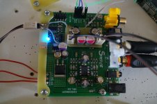
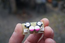
Looks great , 2 Supercaps with 2 electrolytic to decouple .
I listen to you and gave it a try,it worked.
Thank you

I would like to add one thing..the SC and uF in the analog stage opens it up in a big way (way beyond what you see in the THD+N numbers) ..but its rather brute force. Plenty of electrons , plenty of power.
The discrete opamps change this force from 1000hp of a truck ( a Tesla truck for ease of understanding ) into a 1200 HP of a F1 car. (yes it ads power)
Power needs brakes , maneuverability . This is what discreet opamps add. (0-100Kmh in 2.5s / 200kmh to stop in 50m)
The discrete opamps change this force from 1000hp of a truck ( a Tesla truck for ease of understanding ) into a 1200 HP of a F1 car. (yes it ads power)
Power needs brakes , maneuverability . This is what discreet opamps add. (0-100Kmh in 2.5s / 200kmh to stop in 50m)
Last edited:
Democles , we are all here to learn. I learned lots from this forums and its a privilege to give something back.
I have to agree that there is more in a good implementation than THD numbers show. It appears there may be more than one way to get very good sound out of this DAC. What seems to be lacking is any way to compare outcomes of the different but successful ways to get very satisfying sound quality. I have already said that what I am using here as something to compare my modified Chinese DAC to is a Benchmark DAC-3. Don't know if anybody else has said what DAC they are using to compare with (since I think we already agree, THD numbers don't show everything).
Madds,
The problem with Sabre is that they are skimpy with their information. If the chip contains a charge pump to double the voltage, 3.3V would be right in the middle. Basically, it was a wild shot when I mentioned this, it might be ok to follow the Sabre paper on this point, but it deals with a different DAC. Measuring Vout from the DAC is the best way to find out where to bias the opamp. Since all my measurements were done in balanced mode, I didn't bother to measure it when my board was still operation.
Can you please post the schematic along with your questions again, I'll be happy to respond.
Please
- Home
- Source & Line
- Digital Line Level
- ES9038Q2M Board