Appreciated, thanks.Not full-featured WASAPI unfortunately. The drivers work for PCM and SPDIF if the board has a hardware output for it. No Exclusive Mode support. Problem with Windows Sound Engine explained in post #410: https://www.diyaudio.com/forums/digital-line-level/314935-es9038q2m-board-410.html#post5731319
ASIO is highly recommended is all I can say.
Thank you for the link, i do not understand most of this but the little i do is nice to know.ESS does have a little old but at least public advice: http://www.esstech.com/files/4514/4095/4306/Application_Note_Component_Selection_and_PCB_Layout.pdf
Lets try it againLink is broken for me. Happy to take a look if you can repost it.
ES9028Q2M ES9028
Bonus: ES9018K2M + AD823 (it has better pcb pics in the description)
They are about the same price, so i would assume es9028q2m is the superior. (actually board layout seems identical)
Then there is also the es9038q2m the thread is centered around. I would be lying if i said i weren't courious regarding this board, both from its modding potential, the FIR filter jumpers, the digital dithered volume control via 10k pot, etc. I mean who needs a case anyway, i have cardboard boxes around this size.
The only issue is the costly usb to i2s. Maybe i could buy a cheapo i2s interface to begin with, save up later for something better. Drivers for those things are the primary factor keeping me away (and also them costing about as much as the dac board if not more).
I understand PCM2706 samples only up to 48khz, but from my understanding it simply converts the usb digital stream into i2s compatible stream, right? Digital to digital, no digital to analog conversion. Would that be not so super terrible after all for destroying stream quality or is it garbage? CM6631A? Would those affect the sound so much to render the DAC board pointless?
What about these chinese Amanero boards, same issue as XMOS? Sorry for many questions.
I have heard this numerous times too. Just looking at measurements of these chinese boards, even if they're using the same ESS chip the measurements vary wildly. I will assume the es9038q2m board the thread is centered around has a semi decent implementation, enough to be a starting point? Here is a measurement of the board, im sure you're all seen.Thing about dacs is that what the dac chip does is set some limit on the very best a dac board can sound depending on the quality of the surrounding design implementation. In that regard, one can make a very good dac indeed using ES9038Q2M, but it is never cheap or easy. Its the board circuitry implementation that adds cost and complexity if the dac chip is allowed to sound its best. Implementation is huge in terms of the effect on sound quality so much so that some people exaggerate a little and say the dac chip doesn't matter at all, only the implementation does.
Got it, but how do you go about selecting the cap capacitance or am i asking a too broad question?Yes, it only applies to the DC rails powering the opamps. One could try it with the DC rails after the voltage regulators and just before the opamps wherever things are located. Could be the power supply is on the dac board or on a separate power supply board. Mostly, we want the caps as physically close to the opamps as is reasonably possible.
Regards
Last edited:
Lets try it again
I would forget ES9018 of any variety, the newer chips have better technology.
Any Chinese USB board, doesn't matter which USB chip, does not support ASIO nor Native DSD. Some may work with DoP DSD.
Sample rate matters for sound quality, so does DSD. The math says it shouldn't matter, but the math is theory that pertains to a mathematical model of dac. Very useful to understand, but basic theory doesn't fully explain all the practical reasons different dacs sound different from each other, different to different people, and or different to different people under different listening circumstances. Lots of arguments go on around here about such things. In brief, and IMHO, most people who listen to all the different options seem to prefer the sound of higher sample rates, and prefer the sound of DSD. However, what matters for you now is whatever dac solution meets your particular needs at this time. With that, I hope we can skip the arguments 🙂
I understand PCM2706 samples only up to 48khz, but from my understanding it simply converts the usb digital stream into i2s compatible stream, right? Digital to digital, no digital to analog conversion.
It is a dac too. There is a diagram on page 8 of the data sheet with a block that says DAC: https://www.ti.com/lit/ds/symlink/pcm2706.pdf
It is a 16-bit dac too, not something very much like ESS dacs. Some people may like it, don't know.
... Just looking at measurements of these chinese boards, even if they're using the same ESS chip the measurements vary wildly.
Here's the thing about measurements, poor measurements likely indicates something is probably going to sound not very good. On the other hand, great measurements do not necessarily indicate something will probably sound great. The problem or disconnect as I see it is that how people hear does not completely correlate with how we measure. In recent times some dac designers have gotten a lot better and making dacs that measure well, but don't necessarily sound all that good. Too much focus on designing based on measurements and not enough focus on design based on listening. Usually, the best results are obtained by doing both. Also, dacs that sound really good typically measure well too (although there are some exceptions where some people may prefer a few particular dacs that don't measure all that well). In short, mostly it seems that sounding good implies good measurements, but good measurements don't necessarily imply sounding good.
I will assume the es9038q2m board the thread is centered around has a semi decent implementation, enough to be a starting point?
It is probably the best one for modding. The backside of the board has a lot of uncluttered ground plane that is very useful for our purposes. Version 1.07 of the board usually comes with firmware that disables control of the dac chip by the on-board MCU if J1, J2 are installed at the same time. That can also be very convenient for us if we want to control the dac chip in another way, usually using an Arduino or maybe an RPi.
Got it, but how do you go about selecting the cap capacitance or am i asking a too broad question?
What seems to work best for me is a mix is Wima mks4 film caps using 10uf, 22uf, and 33uf values. They aren't cheap caps, so some people opt to use fewer of them or to use other film caps such as DC Link caps. In the case of Wima mks4 film caps, most of the improvement seems to some with the 10uf and 22uf caps. The 33uf caps aren't as effective if used alone, most likely they don't work as well as the smaller ones at higher frequencies. However, Wima does not publish detailed enough measurements to be completely sure about why.
Last edited:
Thanks for your reply Mark
I have a question regarding this that i was thinking about. A dac converts the digital signal to a different domain (analog), which is an encoding process that is well, tricky. But looking at simple digital to digital conversions, lets take an example of a CPU, it takes an input signal, does arithmetic and according to the arithmetic the output is always predictable and exactly what you bargained for (of course there is sometimes error, but this is corrected with error code correction (ECC)). So we could say that a cpu is more or less "bit perfect", as in that it does not lose information, just converts it in a certain way. Going back to the example of the humble PCM, Isnt it merely adapting the digital stream from one format (USB digital stream) to another (I2S), and as such this should not be too much of a lossy process, since it all remains in the digital domain? Of course it seems it will not go above 48khz (actually this part confuses me, because if its just adapting digital signal to another protocol and sending it out to another board which will sample the signal to analog, then that is weird, maybe it is related to the clock on which the interface works (?)), i get the nyquist frequency and all that, but i was thinking to just get the PCM as a starter interface just to evaluate the DAC board initially, or would it mess with the digital stream so much that the venture is pointless, to see if i want to invest more in the project. Would this also be true for the different chipsets (CM6610A, xmos, combo384 etc..)? Sure further improvements could be made with higher sampling rates and DSD and all that, but as i am currently not using that i would not mind to compare this board just apples to apples with crappy signal at first, and later upgrade if i like it.
Thanks for the info, best regards
Because of the licensed drivers? If i get the non generic board you recommended, would that enable me to have system wide ASIO (i.e bypass the windows mixer)? I was reading something about it but i ended up with more questions than answers, so im just going to put it bluntly.Any Chinese USB board, doesn't matter which USB chip, does not support ASIO nor Native DSD. Some may work with DoP DSD.
Looking at the diagram on page 9 it seems like indeed it does have a DAC, however the Is2 and spdif output seems unrelated to it, where the dac merely T's off the line going to IS2 to also provide its output. Picture. Excuse me if i am mistaken.Sample rate matters for sound quality, so does DSD. The math says it shouldn't matter, but the math is theory that pertains to a mathematical model of dac. Very useful to understand, but basic theory doesn't fully explain all the practical reasons different dacs sound different from each other, different to different people, and or different to different people under different listening circumstances. Lots of arguments go on around here about such things. In brief, and IMHO, most people who listen to all the different options seem to prefer the sound of higher sample rates, and prefer the sound of DSD.
It is a dac too. There is a diagram on page 8 of the data sheet with a block that says DAC: https://www.ti.com/lit/ds/symlink/pcm2706.pdf
It is a 16-bit dac too, not something very much like ESS dacs. Some people may like it, don't know.
I have a question regarding this that i was thinking about. A dac converts the digital signal to a different domain (analog), which is an encoding process that is well, tricky. But looking at simple digital to digital conversions, lets take an example of a CPU, it takes an input signal, does arithmetic and according to the arithmetic the output is always predictable and exactly what you bargained for (of course there is sometimes error, but this is corrected with error code correction (ECC)). So we could say that a cpu is more or less "bit perfect", as in that it does not lose information, just converts it in a certain way. Going back to the example of the humble PCM, Isnt it merely adapting the digital stream from one format (USB digital stream) to another (I2S), and as such this should not be too much of a lossy process, since it all remains in the digital domain? Of course it seems it will not go above 48khz (actually this part confuses me, because if its just adapting digital signal to another protocol and sending it out to another board which will sample the signal to analog, then that is weird, maybe it is related to the clock on which the interface works (?)), i get the nyquist frequency and all that, but i was thinking to just get the PCM as a starter interface just to evaluate the DAC board initially, or would it mess with the digital stream so much that the venture is pointless, to see if i want to invest more in the project. Would this also be true for the different chipsets (CM6610A, xmos, combo384 etc..)? Sure further improvements could be made with higher sampling rates and DSD and all that, but as i am currently not using that i would not mind to compare this board just apples to apples with crappy signal at first, and later upgrade if i like it.
Since you asked, i will tell you. I bought a hifimediy UAE23 (es9023, sa9023) 1.5 years ago, and recently it has developed digital "buzzing" and producing audible harmonics (for example easily heard when playing sine waves), the noise floor is quite noticable as well. I was just looking to replace it with the best i could muster for under 40-50$ initial investment (since im poor as dirt). The 9039q2m seems like what im looking for, and im a big sucker for things you can tinker with, but the i2s issue is annoying from a cost and complexity (with drivers working or not working, lower portability because i need to carry drivers with me on every machine i use it at, etc.) standpoint, so now i am looking what are my options.However, what matters for you now is whatever dac solution meets your particular needs at this time. With that, I hope we can skip the arguments 🙂
This explains the tube folks 😀 Ok, ok just joking, dont lynch me, i like tubes too.Here's the thing about measurements, poor measurements likely indicates something is probably going to sound not very good. On the other hand, great measurements do not necessarily indicate something will probably sound great. The problem or disconnect as I see it is that how people hear does not completely correlate with how we measure. In recent times some dac designers have gotten a lot better and making dacs that measure well, but don't necessarily sound all that good. Too much focus on designing based on measurements and not enough focus on design based on listening. Usually, the best results are obtained by doing both. Also, dacs that sound really good typically measure well too (although there are some exceptions where some people may prefer a few particular dacs that don't measure all that well). In short, mostly it seems that sounding good implies good measurements, but good measurements don't necessarily imply sounding good.
Thanks for the info, best regards
Last edited:
For the cheapest USB solution, probably a cheap Chinese XMOS or Amanero clone would be best, at least they can work with 24-bit audio and hit pretty high PCM sample rates. CM6631A can work too.
OTOH, if you used the 16-bit dac as a USB interface it would be limited to 16-bit I2S. Wouldn't make much sense to buy one for use with a Sabre dac and throw away bits of resolution and possible use at higher sample rates. However, if you already have one you can use without additional cost it may be worth a try.
Also, the Chinese ESS dac boards generally have SPDIF, TOSLINK, and I2S inputs. Just mention that in case you already have any of those available without added cost.
Last edited:
Hmm, guess i'll go with this unit and hope the drivers work.For the cheapest USB solution, probably a cheap Chinese XMOS or Amanero clone would be best, at least they can work with 24-bit audio and hit pretty high PCM sample rates. CM6631A can work too.
You're absolutely right, i was just wondering at that 16bit 48khz resolution, would it be be a faithful reproduction of the signal, given how its in the same domain, Digital-Digital?OTOH, if you used the 16-bit dac as a USB interface it would be limited to 16-bit I2S. Wouldn't make much sense to buy one for use with a Sabre dac and throw away bits of resolution and possible use at higher sample rates. However, if you already have one you can use without additional cost it may be worth a try.
Also stupid question, but the closes for a power supply i found laying around is a DC12V 5A brick, the board specifies for DC15V on the jack, would that work? Furthermore it says something about dual voltage, but i dont know anything about that.
Hmm, guess i'll go with <Chinese XMOS> and hope the drivers work.
IME, they work fine for PCM, given the caveats about Windows resampling, etc.
You're absolutely right, i was just wondering at that 16bit 48khz resolution, would it be be a faithful reproduction of the signal, given how its in the same domain, Digital-Digital?
The dac chip can accept 16-bit I2S okay. If you ever wanted to play a hi-res file, having 24-bit capability would be nice.
...for a power supply i found laying around is a DC12V 5A brick, the board specifies for DC15V on the jack, would that work?
If we are talking about the ES9038Q2M board in this thread, 12v DC can work. In that case a jumper (J6?) needs to be soldered to configure for single supply operation.
Furthermore it says something about dual voltage...
Better to operate the dac from linear +-15v supplies if there is a choice. Probably best to avoid cheap DC-DC converters at any cost, better to run on a single +12v (linear supply). Same concern for SMPS brick supplies as for DC-DC converters. Switching supplies tend to affect dac sound in a bad way unless extremely well designed. If you must use some kind of SMPS, try to find the least bad one possible, and maybe try putting some ferrite cable clamps on the outputs to help get some of the remaining RF switching and ringing hash out of the power rails. Putting the SMPS in its own sealed metal box can help (although I found one SMPS brick that went nuts if metal or a finger came too near one spot on top of the brick). Lining the inside and outside of the metal box with adhesive-backed copper foil can help some more too.
If we are talking about the ES9038Q2M board in this thread, 12v DC can work. In that case a jumper (J6?) needs to be soldered to configure for single supply operation.
Better to operate the dac from linear +-15v supplies if there is a choice. Probably best to avoid cheap DC-DC converters at any cost, better to run on a single +12v (linear supply). Same concern for SMPS brick supplies as for DC-DC converters. Switching supplies tend to affect dac sound in a bad way unless extremely well designed. If you must use some kind of SMPS, try to find the least bad one possible, and maybe try putting some ferrite cable clamps on the outputs to help get some of the remaining RF switching and ringing hash out of the power rails. Putting the SMPS in its own sealed metal box can help (although I found one SMPS brick that went nuts if metal or a finger came too near one spot on top of the brick). Lining the inside and outside of the metal box with adhesive-backed copper foil can help some more too.
Yeah the dual supply converter seemed supremely sketchy, so i was hoping 12V linear would be fine. Thank you for the info, it shall be so.
If you can swing it, a proper +/- supply would be best, as mentioned. I wouldn’t recommend messing with a resonant type of power supply, especially with metallic cases unless you have fire insurance.
The drivers are available from
Drivers - I2S over USB Audio
Wima MKS are not necessarily expensive caps either.
The drivers are available from
Drivers - I2S over USB Audio
Wima MKS are not necessarily expensive caps either.
Hi Mark,
I was reading this thread and your post list number 4, and it's quite a valiant effort, however one thing is a trend i've noticed. The posts briefly describe the modification and the reasoning for it, however i am left clueless as how to perform said modification based on an attached picture of the mod.
For example: post 377, post 2290, post 621
It is all very impressive indeed but, and im sure maybe you can, i cannot reproduce such a work based on pictures 😱. Is that maybe that's just the required barrier for entry into modding this board, because other alternatives are time prohibitive (ie. making schematics and guides for the mods)? The reason why i mention this is that one of the posts i've read in that list was a post regarding how the thread views and engagement was dropping, so i thought i would share my experience.
After going trough all the posts in the post list 4 i have deduced the only mods i even know what is going on is just replacing the clock with a crystek 575 100mhz, and adding some filtering caps inline with the DC input (before it connects to the board).
EDIT: found the schematic for the avcc, nice
Regards
Last edited:
Hi Zbunjen,
Long story. When I started out trying to experiment around with modding a cheap dac board it wasn't because I needed to, it was out of curiosity. I already had what I thought was a perfectly fine dac, last one I would probably ever need.
When I started out on that it was after retiring from a career as an EE in medical research and treatment. Didn't know much about dac boards. Since there wasn't much published info on what would be needed to make the dac sound good (to me), I starting modding these boards to find out. Along there way there were some misunderstandings on my part about some things, but by comparing the sound of the modded dac to my commercial dac I could tell if I was going more or less in the right direction. Anyway, I learned quite a bit between when I started and now, and really, one could spend many years on nothing but dacs. There is a very large body of knowledge I will never get to, I'm sure. Started too late in life and don't care enough to work any harder at it, I guess.
Okay, I explained the foregoing so hopefully it will make better sense why I posted what I have. It was not intended to be a tutorial, since it has been me doing most of the learning. Also, I still don't see a way for me to make it tutorial for a beginner to electronics. That would have to include a whole lot more than just dac boards.
Of course, don't know what your background is, but you did say you didn't understand much of the ESS document I linked to that shows some output stages and parts of AVCC circuitry among other things. That suggests you may not be to up on how to read data sheets.
Seemed to me that the pictures I posted (which are as high res as I could post, to see them full size you need to open them, then click on the white X in the lower left corner), along with data sheets for components should be enough for an experienced person to get the essence of what was done and to get an idea of how to do something pretty much like it, or maybe to see how something somewhat different could be done.
In addition, people have always been encouraged to ask specific questions if they need help/advice. Obviously, there is only so much that can be done in the way of explanation in forum text and a few pictures. Given that people modding dacs are spread out all over the world it means most will have to figure some things out as they go along mostly working alone.
What seems to have happened is that quite a few people had initial interest in the modding project based on hopeful belief that it should be fairly easy to make the dac board sound quite a bit better. It turned out that to make the dac sound as good as I could manage to figure out was quite involved and required throwing away almost all the components on the board except the dac chip. Lots of work involved in fabricating more complex circuitry that makes for a better implementation. Not many people were up for all that, especially with too many other things going on in life. Some people were intimidated by the prospect of SMD soldering and wouldn't even try it once. Some decided the whole thing was too hard so they went looking for easier solutions.
It kind of seems to me that most of the people here are into diy as a means to save money. They think (or used to think) cheap Chinese dac boards are bargains and easily made into something better because the people who designed the boards didn't know what they were doing. No so. The designers make the boards at super low cost using the cheapest possible components except for the dac chip which is needed for the marketing claims about performance. Those guys know what they are doing, at least they do by now, they have been at it quite awhile.
Bottom line, the dac boards are pretty cheap, they can be modded as much or as little as one has interest to do, and or as one as time and money to invest. To make a great dac out of one is not cheap, quick, or especially easy, but it can be done. That's what I found out on this project.
Now, for whatever reasons these dac boards are old news and the initial excitement about a new ESS dac chip has mostly passed. People have done their modding as much as they want, or have found other dacs to use instead. Mostly just a few latecomers now, although one or two people are still working on theirs.
Last edited:
Should have mentioned in the last post that some schematics are available in post #3003: https://www.diyaudio.com/forums/digital-line-level/314935-es9038q2m-board-301.html#post5577605 ...also please see the posts after that discussing differential outputs.
In addition, an output stage board mod has been described:Dropbox - Output Stage Instructions.zip
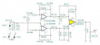
Regarding the output stage schematic we used, it sounds good but a commercial output stage was posted in this thread that is rather similar, mainly the impedances around the differential summing stage are lower. The lower impedances are likely a little better when using OPA1612 opamps, but I haven't listened for differences myself. Please see attachment below. One might use the basic design of our output stage project but change some parts values to match the schematic below to try it. If doing that, please be sure to use equally good quality components for the resistors and caps.
There is one more thing to mention here: the voltage level for Vref, which is produced on our AVCC mod board, might need to be changed to reduce distortion in the output stage (ESS 'hump' removal). If you are thinking about doing the mods, there were some posts on that subject I can help look up for you.
In addition, an output stage board mod has been described:Dropbox - Output Stage Instructions.zip
Regarding the output stage schematic we used, it sounds good but a commercial output stage was posted in this thread that is rather similar, mainly the impedances around the differential summing stage are lower. The lower impedances are likely a little better when using OPA1612 opamps, but I haven't listened for differences myself. Please see attachment below. One might use the basic design of our output stage project but change some parts values to match the schematic below to try it. If doing that, please be sure to use equally good quality components for the resistors and caps.
There is one more thing to mention here: the voltage level for Vref, which is produced on our AVCC mod board, might need to be changed to reduce distortion in the output stage (ESS 'hump' removal). If you are thinking about doing the mods, there were some posts on that subject I can help look up for you.
Attachments
Last edited:
Mark, as it was mentioned some time ago, then upon the "full" mod only DAC chip remains (and some connectors perhaps). so at the moment I am working on a PCB layout based on the knowledge from this thread. just for fun of course 🙂
Hi eziitis,
Just wondering how the PCB project is coming along?
cheers
Mark
Last edited:
Try to avoid MEMS for audio applications.Hmm, guess i'll go with this unit and hope the drivers work.
MEMS oscillators appear suited to high vibration environments, to non-critically timed applications, and to applications where the signal-to-noise ratios are not critical.
If you want to read more information, search on Google "MEMS vs. crystal based oscillators"
Couple of simple/daft questions for a Sunday morning, apologies in advance.
I have some amazon vouchers so thought I’d use them on a project dac, don’t need usb and coax and toslink are fine to start with. So, I am looking to get the SM PCB v1.07 board, a full wave rectified power supply board to provide the power and a dual 9v transformer (give 12.7v +/0/- dc supply).
If anyone could answer the following question then that would help get me started:
1) I want to use the onboard volume jumpers so firstly what is the socket so I can get a plug for the pot
2) also is a lin or log 10k pot best to control the volume.
3) of the amazon suppliers of this board are any more reputable than others (using the U.K. site)
Finally, I understand that this is not the ultimate in hifi and there are known issues but as a simple project to get me going I think it is about as simple as it get to start with. I can then work through the various modes once up and running.
Also I am interested to to see how it stacks up against my dual WM8741 Audio GD dac that has a few simple mods (dir9001 controller, amanero usb and I have added a stepped attenuator to the outputs for use with my active speakers).
Thanks in advance for replies.
Yes, that's absolutely understandable, and i cant expect or "demand" anything from you, so i will try to do the best with what my noggin can do and piece together some modifications.Hi Zbunjen,
Long story. When I started out trying to experiment around with modding a cheap dac board it wasn't because I needed to, it was out of curiosity. I already had what I thought was a perfectly fine dac, last one I would probably ever need.
When I started out on that it was after retiring from a career as an EE in medical research and treatment. Didn't know much about dac boards. Since there wasn't much published info on what would be needed to make the dac sound good (to me), I starting modding these boards to find out. Along there way there were some misunderstandings on my part about some things, but by comparing the sound of the modded dac to my commercial dac I could tell if I was going more or less in the right direction. Anyway, I learned quite a bit between when I started and now, and really, one could spend many years on nothing but dacs. There is a very large body of knowledge I will never get to, I'm sure. Started too late in life and don't care enough to work any harder at it, I guess.
Okay, I explained the foregoing so hopefully it will make better sense why I posted what I have. It was not intended to be a tutorial, since it has been me doing most of the learning. Also, I still don't see a way for me to make it tutorial for a beginner to electronics. That would have to include a whole lot more than just dac boards.
You would be right, my background is in software development, i have no formal training in EE. This is both a pro because i enjoy the feeling of learning a bunch of things when you're at the beginning of the learning curve, but also a con because i have to annoy everyone on this forum with my questions (at least im bumping the thread). I have had previous experience building some load cell setups with arduino, and doing some DIY boards, but this is on a bit of a higher level than that. I had a phase where i watched EEVblog regularly, for what its worth 😱.Of course, don't know what your background is, but you did say you didn't understand much of the ESS document I linked to that shows some output stages and parts of AVCC circuitry among other things. That suggests you may not be to up on how to read data sheets.
This paragraph could also be used a pretty good analogy for human life development as well.What seems to have happened is that quite a few people had initial interest in the modding project based on hopeful belief that it should be fairly easy to make the dac board sound quite a bit better. It turned out that to make the dac sound as good as I could manage to figure out was quite involved and required throwing away almost all the components on the board except the dac chip. Lots of work involved in fabricating more complex circuitry that makes for a better implementation. Not many people were up for all that, especially with too many other things going on in life. Some people were intimidated by the prospect of SMD soldering and wouldn't even try it once. Some decided the whole thing was too hard so they went looking for easier solutions.
Interesting, i've looked it up, thank you for bringing it to my attention.Try to avoid MEMS for audio applications.
MEMS oscillators appear suited to high vibration environments, to non-critically timed applications, and to applications where the signal-to-noise ratios are not critical.
If you want to read more information, search on Google "MEMS vs. crystal based oscillators"
Here is my intention i have, based on some researching, reading this thread, a big help was also a pdf i found somewhere in this thread (i cant find the post number anymore), and reading this thread, here is my modification intention.
1.110uF Capacitor bank on DC input (i have also considered the Nazar regulator you mentioned, however i dont feel confident enough at the moment)
2. two lt3042 linear regulators (or maybe lm317?)with 100uf caps for AVCC (i've read the post about super regs you wrote regarding 1/f noise below 1khz, however i assume this is more of a technical consideration than one that will practically cripple the audio below 1khz). Seems like both will take DC15V input and give 3.3V output.
3. 4.7uF cap on the DVDD
4. Roll with opa1612
5?. I wonder if i can remove the 3.3v digital regulator already on the board, leech off one of the avcc linear regulators outputs (or just get another lt3042 because this sounds like a bad idea because then load will be asymetrical on avcc_r and avcc_l right?),and just jumper the 3.3v and GND to the pads.
I have also attached a picture to show roughly the execution. Of course, the cable runs will be shorter, i just drew it exaggerated to show more clearly. Click me for pic
Do you think what i have just written breaks many rules of EE, or is it reasonable enough of a plan? I hope i have understood these modifications right.
What do you think is the most "noticable improvement" modification to do on these boards? Linear regulator to minimise input distortion with a good voltage reference?
2. two lt3042 linear regulators...for AVCC
We now recommend to try to avoid LDOs such as LT3042 for AVCC, simply because they don't sound good there. Never tried using two LM317 for that, don't know if they work down to 3.3v. Best is a dual opamp supply, because it sounds best for that application, which is unusual because it has zero PSRR.
EDIT: I did try ADM7150 (or other similar 15v tolerant ADM71xx family) LDO regulators for AVCC once (using a Twisted Pear AVCC module). Found that sound was somewhat distorted. Experiments showed that running the LDOs from increased input voltage helped improve sound quality. For the LDOs I tried 7v input was enough. Sound quality was also improved by increasing LDO output current: A 33-ohm, 1/2-watt resistor was attached from each LDO output to ground. That also helped sound quality. It is known that voltage regulators are often not entirely linear, they may regulate best at someone higher than minimum input voltage and with moderate output current. I guess that solution was tolerable. However, I later replaced the LDOs with a dual AD787 opamp regulator which sounded better.
Note: Chinese dual LM317 supplies are typically +- supplies with LM317/LM337. Good for opamps, but not as good sounding as NJM7815/NJM7915.
3. 4.7uF cap on the DVDD
Isn't there a cap on that already? If so, it should be fine as is. (at least for now, replacing caps around the dac chip doesn't help much, maybe useful as a last step for a little more RF stability, probably no audible difference at this point).
4. Roll with opa1612
The existing single opamp output stage is called a 'voltage mode' output. THD is down around -70dB that way which is pretty bad. With a proper 'current mode' output stage it is possible to get down closer to -120dB distortion which is very good.
5?. I wonder if i can remove the 3.3v digital regulator already on the board, leech off one of the avcc linear regulators outputs (or just get another lt3042 because this sounds like a bad idea because then load will be asymetrical on avcc_r and avcc_l right?),and just jumper the 3.3v and GND to the pads.
The existing 3.3v regulator is fine to leave in place for the MCU. If you can't afford to properly remove AVCC from the 3.3v bus with its own regulator, at least hanging some large value electrolytics from each AVCC pin to ground will help. 1800uf x3 per AVCC pin can be attached to the existing AVCC cap pins where the come out on the bottom side of the board.
To further clean up the power supply situation, a few small 3.3v LDO regulators can be attached to the bottom of the dac board and used to power things like clock, DVCC, and VCCA. If no money for it or if too hard to do at this time, then skip those for now, would be my advice. Of if you can afford one LT3042 or LT3045 is could b used to power all the above. At least the MCU could be on the old regulator.
I have also attached a picture to show roughly the execution. Of course, the cable runs will be shorter, i just drew it exaggerated to show more clearly.
Do you think what i have just written breaks many rules of EE, or is it reasonable enough of a plan? I hope i have understood these modifications right.
Grounds and output leads from any external voltage regulators, other than for the output stage, should be as short as possible. Even better, the ground plane of the regulator should be soldered directly to the dac board ground plane so the ground wire impedance is closer to zero.
What do you think is the most "noticable improvement" modification to do on these boards? Linear regulator to minimise input distortion with a good voltage reference?
Biggest improvement probably with three opamp output stage running on +-15v, and opamp AVCC supply. If can't do the latter, then large electrolytics (3x 1800uf per AVCC pin) can help until you can.
Replacing default 3.3v regulator on the board with something better will help audibly too, although a single regulator for all 3.3v loads would still be very compromised.
After some or all of the above fixes, a clock module replacement will provide audible improvement.
At any point along the way that you can connect to I2C bus without MCU activity there (like if you get a 1.07 board that halts MCU on I2C with J1,J2), then you could drive the dac I2C and I2S from RPi using eslei's driver setup for multiple audible benefits.
Last edited:
The TP AVCC module I mentioned previously was Trident AVCC-SR: Trident-SR
...might be better than LT304x for AVCC if an opamp regulator isn't practical for ES9038Q2M. Would suggest reading the part numbers on the regulator chips to verify they are types rated for 15v maximum input volts (even though 7v is enough for any audible improvement over running them at 5v). 33-ohm load or similar would also be advised.
Regarding LT304x, never tried them for AVCC myself, but others have then switched to opamp AVCC regulation. Opamps always reportedly sound best and can work with ESS Sabre dacs up to and including ES9028PRO. (The ES9038PRO requires too much current for opamps.)
If someone wanted to try to optimize LT304x for AVCC, they would have to run their own sound quality experiments. Don't know why bother though, since there is already a very good solution in opamps. Could be we would find opamps are best for AK4499 too, haven't tried it yet. Should be easy enough in the 22ma output mode, such as is used for DSD volume-bypass mode.
Last edited:
I'm back on the case now, received my replacement ES9038Q2M 1.07 board that works with the J1/2 so the Pi/Arduino option is open.
I've desoldered the DACL/R resistors breaking the 'bridge' between the DAC and the output and used my TwistedPair IVY III to do the i/v work. I'm trying to do this neater than last time by using pin connectors to help with the construction/deconstruction.
Next I'll replace the AVCC caps with the pair of 3300uf caps, desoldering the resistors to use the pads to solder on my dual opamp regulator. I'm still trying to work out if using a plugin (pin connector) board with the caps and power lines is the best going forward.
The other 3.3v sources (not the MCU) will be separated from the board and powered by other LDOs.
The IVY-III is powered as before with around 15uf of PP caps of varying sizes per line. I have quite a few decent 4.7/3.3uf caps but they are bulky and I'd rather use them in crossovers. What's the thoughts on MKTs in this position?
This time I'm not going near the crystal until I get some of that ChipQuik and have plenty of practice!!!!!
Hello Mark, thank you for the patience and the detailed reply.
I think i could build your LTC6655BHMS8-3.3 and LME49720 dual opamp AVCC supply, however a single LTC trough mouser or digikey would run me 35€ (primarily shipping), then add on an LME, other components etc. Even on ebay the LTC runs over 20$ and ill probably receive a fake. This got me thinking and with a bit of snooping around i came to this "compromise" solution of the LT3042.
If you say it will sound worse than the default components on the board, ill take your word for it.
The LM317 allegedly says DC Output Voltage: 1.25 ~ 30V adjustable, i guess that's ok, but don't know if you approve of those ones. Seems to be a 2 post input labeled just "AC IN" (even though description says DC is also an acceptable input). At any rate wouldnt that be a + and ground connection? Because you're definitely right about the ebay NJM7815 board and its indeed for double supply DC, 3 post connection.
We now recommend to try to avoid LDOs such as LT3042 for AVCC, simply because they don't sound good there. Never tried using two LM317 for that, don't know if they work down to 3.3v. Best is a dual opamp supply, because it sounds best for that application, which is unusual because it has zero PSRR.
EDIT: I did try ADM7150 (or other similar 15v tolerant ADM71xx family) LDO regulators for AVCC once (using a Twisted Pear AVCC module). Found that sound was somewhat distorted. Experiments showed that running the LDOs from increased input voltage helped improve sound quality. For the LDOs I tried 7v input was enough. Sound quality was also improved by increasing LDO output current: A 33-ohm, 1/2-watt resistor was attached from each LDO output to ground. That also helped sound quality. It is known that voltage regulators are often not entirely linear, they may regulate best at someone higher than minimum input voltage and with moderate output current. I guess that solution was tolerable. However, I later replaced the LDOs with a dual AD787 opamp regulator which sounded better.
Note: Chinese dual LM317 supplies are typically +- supplies with LM317/LM337. Good for opamps, but not as good sounding as NJM7815/NJM7915.
I think i could build your LTC6655BHMS8-3.3 and LME49720 dual opamp AVCC supply, however a single LTC trough mouser or digikey would run me 35€ (primarily shipping), then add on an LME, other components etc. Even on ebay the LTC runs over 20$ and ill probably receive a fake. This got me thinking and with a bit of snooping around i came to this "compromise" solution of the LT3042.
If you say it will sound worse than the default components on the board, ill take your word for it.
The LM317 allegedly says DC Output Voltage: 1.25 ~ 30V adjustable, i guess that's ok, but don't know if you approve of those ones. Seems to be a 2 post input labeled just "AC IN" (even though description says DC is also an acceptable input). At any rate wouldnt that be a + and ground connection? Because you're definitely right about the ebay NJM7815 board and its indeed for double supply DC, 3 post connection.
Would the OPA1612 then make the DAC run in current mode, or are you saying this is a bad modification?The existing single opamp output stage is called a 'voltage mode' output. THD is down around -70dB that way which is pretty bad. With a proper 'current mode' output stage it is possible to get down closer to -120dB distortion which is very good.
Oh i see, this is basically just taking the existing 2 AVCC caps and just adding a lot of more capacitance inline with it, if i understood correctly? 3x caps instead of 1x (tantalum, ceramic, etc) is to absorb different high frequency spectrum in the DC signal?The existing 3.3v regulator is fine to leave in place for the MCU. If you can't afford to properly remove AVCC from the 3.3v bus with its own regulator, at least hanging some large value electrolytics from each AVCC pin to ground will help. 1800uf x3 per AVCC pin can be attached to the existing AVCC cap pins where the come out on the bottom side of the board.
I could afford several LT3042, but, didn't you just suggest above not to use it for AVCC (so LT3042 is only bad for AVCC and not other supply needs)? In my original plan i have intended to buy 2x LT3042 for AVCC, T off one of them into 3.3v and ground as a new supply for the MCU (wouldn't that necessitate the removal of the old MCU regulator? Why would the MCU need 3.3v from 2 sources?)To further clean up the power supply situation, a few small 3.3v LDO regulators can be attached to the bottom of the dac board and used to power things like clock, DVCC, and VCCA. If no money for it or if too hard to do at this time, then skip those for now, would be my advice. Of if you can afford one LT3042 or LT3045 is could b used to power all the above. At least the MCU could be on the old regulator.
Yep, gotcha 😀. I just drew the thing at the side of the board to be more easily seen against the white background, in reality i would not run such long connections to anything.Grounds and output leads from any external voltage regulators, other than for the output stage, should be as short as possible. Even better, the ground plane of the regulator should be soldered directly to the dac board ground plane so the ground wire impedance is closer to zero.
Excellent, i will keep this fix benefit order in mind.Biggest improvement probably with three opamp output stage running on +-15v, and opamp AVCC supply. If can't do the latter, then large electrolytics (3x 1800uf per AVCC pin) can help until you can.
Replacing default 3.3v regulator on the board with something better will help audibly too, although a single regulator for all 3.3v loads would still be very compromised.
After some or all of the above fixes, a clock module replacement will provide audible improvement.
This part had me really intrigued when i saw in the thread, but i didnt look much into this aspect yet. I think for me this would come after all the hardware modifications.At any point along the way that you can connect to I2C bus without MCU activity there (like if you get a 1.07 board that halts MCU on I2C with J1,J2), then you could drive the dac I2C and I2S from RPi using eslei's driver setup for multiple audible benefits.
Hmm i just checked it out, about 60$ shipped to my country, which is a bit cost prohibitive for me currently. I think either i will do your suggested 3x 1800uF, or get 2x LT3042 (or LM317). It's really unfortunate trying to do something but having to cross off everything decent off the list..The TP AVCC module I mentioned previously was Trident AVCC-SR: Trident-SR
...might be better than LT304x for AVCC if an opamp regulator isn't practical for ES9038Q2M. Would suggest reading the part numbers on the regulator chips to verify they are types rated for 15v maximum input volts (even though 7v is enough for any audible improvement over running them at 5v). 33-ohm load or similar would also be advised.
Regarding LT304x, never tried them for AVCC myself, but others have then switched to opamp AVCC regulation. Opamps always reportedly sound best and can work with ESS Sabre dacs up to and including ES9028PRO. (The ES9038PRO requires too much current for opamps.)
Last edited:
Good work Damian. Can I ask if you drive a GT3?!
Quick question. I have the 1.07 ver in a kitchen system. Handy as it is on all day and so good for burning in new new modifications.
Fine with optical from Google chromecast audio. Optical from a sky q mini box I get very brief intermittent audio drip drop outs. Using a 3metre long optical cable. Could this length be my issue?
- Home
- Source & Line
- Digital Line Level
- ES9038Q2M Board