Hi guys. Hope youre all doing well. Just checking in as I haven't spoken here in a while. I need to read back and see where we are. I'm still planning to follow this build and have bought a few boards and bits mentioned on the PDF written.
Question for Mark. I bought a new tv which is going to be my digital source. However, it Only has optical out. No SPDIF. Will this be a problem now to follow this build?
Thanks.
Question for Mark. I bought a new tv which is going to be my digital source. However, it Only has optical out. No SPDIF. Will this be a problem now to follow this build?
Thanks.
Hi Alex,
TOSLINK is essentially optical SPDIF. However, ADAT and some encrypted Dolby streams also use the same optical interconnects. So long as the TV signal is stereo or mono and not encrypted then there should be no problem. If you want to go the way I like to do using AK4137, and if the TV audio is to be upsampled and converted to DSD along with USB music sources then you would probably want the higher cost AK4137 board that includes SPDIF and TOSLINK inputs:
HIFI AK4137 DAC SRC flagship high-end audio 786K 32Bit DSD256 DSD IIS conversion | eBay
The usual ways we recommend to get started include building an output stage (schematic and instructions available), an AVCC supply, and replacing the clock. The built-in 3.3v regulator on the dac board is fine for running the MCU, but the Clock, DVCC, and VCCA sound best with dedicated 3.3v regulators for each one. Of course, external +-15v and +5v power supplies are recommended, and either the +-15v should be augmented with film cap filtering, or alternatively some high performance audio +-15 regulators should be considered. Twisted Pear offers Placid HD shunt regulator kit, the diyaudio store sells boards to make Jung-Didden regulators, and our forum member eziitis recommends low cost nazar regulators for +-15 and for AVCC. One thing most people never end up doing, but should learn how to do is program the dac control registers with an Arduino or other MCU of their choice. We can provide a fair amount of info to support as much or as little as you would like to do. For the very best results and to compete with serious commercial dacs, nothing can be neglected, since the really good commercial dac makers sure try hard not to neglect anything.
Then there is the AK4137 board to consider. It can be left as, or more work can be done to clock it synchronously with the dac clock (for very best sound quality). However, no reason to go that far if all the other stuff isn't done first.
Last edited:
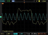
Recently, I replaced some of the LVDS clock cables to and from the clock divider board for modded dac#2. This time best sound quality is with the 12.5MHz DSD clock timing from AK4137 perfectly aligned (as well as my 100MHz scope can show) with the dac 100MHz MCLK (measured at a dac GPIO pin). In this case, perfectly aligned means the same relative clock timing as the dac chip would produce if it were generating the I2S/DSD clocks in master I2S mode. That is a little different from what I found produced best SQ with the previous cables, although it could be there was some jitter or something that caused it to sound best with a little bit different timing. The sensitivity to timing is similar to the effects of other things we try to get right such as distortion compensation, power supply quality, etc. In other words, it is audible and subjectively similar in character to some combination of low level jitter and low level distortion. Adjusted to where it sounds best makes SQ more pleasant, and the adjustment is fairly sensitive. Perhaps 150ps or less change in relative clock timing can produce very small audible changes. 300ps - 450ps change produces more easily heard effects. For me, I don't think I would want it to be off by more than 150ps from whatever produces best subjective SQ. That might amount to something like the difference in timing caused by a 1" change in the length of a piece of coax cable (depending on the particular cable propagation delay, often somewhere around 2ns per foot).
Attachments
Mark,
I don't know what's going on with you clock signals but they look very noisy, maybe lot's of PS noise or ground bounce.
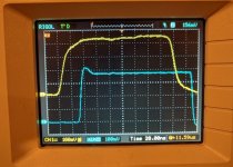
Ref below a pic of bitclock OP of one of my OCXO driven reclocker. The reclocker was implemented with Potato logic flip flop. The yellow signal is the input before reclocking.
The slight overshoot is most likely an impedance mismatch with Cro leads which I could control with OP resistor however I wanted to keep leading edge as fast as possible.
This is only 2.8MHz, however you can still see that it is very well controlled.
Maybe you could try Potato logic dual FF for freq division. I had excellent results with them. I believe Ian also used them for reclocking on the FIFO.
cheers
Terry
I don't know what's going on with you clock signals but they look very noisy, maybe lot's of PS noise or ground bounce.
Ref below a pic of bitclock OP of one of my OCXO driven reclocker. The reclocker was implemented with Potato logic flip flop. The yellow signal is the input before reclocking.
The slight overshoot is most likely an impedance mismatch with Cro leads which I could control with OP resistor however I wanted to keep leading edge as fast as possible.
This is only 2.8MHz, however you can still see that it is very well controlled.
Maybe you could try Potato logic dual FF for freq division. I had excellent results with them. I believe Ian also used them for reclocking on the FIFO.
cheers
Terry
Attachments
I don't know what's going on with your clock signals...
Hi Terry,
Yes, we agree you don't know what is going on with the clock signal scope shot I posted. We have already been through this once, IIRC, the last time I posted I picture of the same signals.
Have no idea why you have started talking about clock dividing when there is no divided clock shown at all in the pic I posted.
We probably can agree that taking a nice picture of 2.5MHz (and only one signal at a time) is often pretty easy.
To kind of repeat some of what I said last time, and in case there is unstated concern by others regarding the appearance of the signals in the picture I posted, the picture includes an LVCOMS AK4137 generated DSD clock signal originating on another PCB, traveling through pin headers and ribbon cable and arriving at another PCB where it is used. The other signal shown is an LVCMOS dac chip generated 100MHz clock signal that drives an LVDS converter chip and which was captured with a 100MHz scope. That signal is most likely attenuated and phase shifted due to scope bandwidth limitations, and certainly lacking accurate edge information, unless of course the scope tries to do digital tricks to compensate for those things it might, which seems pretty doubtful.
Regarding the waveform aberrations that can be seen in the picture, they are neither caused by random noise, nor asynchronous deterministic noise (signal averaging was used to minimize possible effects those things). Some of what you see is waveform distortion caused by the cheap probes (their fidelity was compared with a much better Tek probe of the same rated bandwidth, but only one Tek probe and I wanted to use matched probes for the pic). Some aberration is an effect of less than ideal probe grounding since I had to hold both probes in awkward positions down inside a deep shielded enclosure while operating the scope with my other hand. Remaining waveform distortion is largely attributable to impedance discontinuities along the paths where the signals run (including any distortion caused by probe capacitance).
The reason the signals travel around as they do is because the project is still a very early stage experiment. Very different from your case where you know in advance exactly what you want to do.
Also, I wanted to show what someone else modding a dac as I did and using a similar scope might expect to see.
The foregoing having been said, I can see the need for a better scope when working with 100MHz clock signals. Unfortunately, I have equipment budget constraints that limit what is realistically likely to be possible. Nonetheless, I am working on trying to get a somewhat better scope so I can at least take more accurate pictures of what may be slightly ugly looking signals. I wouldn't want signals like that in a finished product or if I thought they were hurting SQ to any significance extent, but for a lab monstrosity, the dac works quite well. Clearly sounds subjectively better and more listenable than a dac that Stereophile not very long ago rated A+ and that sold for around $3,500. And, yes, I recall you questioned the reliability of Stereophile ratings, something that Claude recently talked about at length (Thanks again, Claude!), so we both have the same info there.
Maybe one of these days I will try building a dac more in keeping with the formula you like use, Terry, but for now I still want to see what can be done at low cost and for very good sound quality without having to rule out real-time SPDIF or AES compatibility.
Last edited:
This thread provides so many options but I thought I'd start with some of the basics.
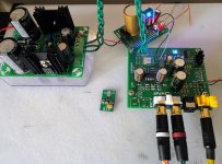
I've started to separate the power supplies for the DAC and the output. Using an existing LM317/337 for the +/- 15V for the output stage. I quickly built a simple regulated 7805 and 2x1117 board to provide a 5V and 2x3V, the 7805 has been replaced with a Dexa NewClass D. The Dexa is feeding the 1117s as well as the 5v for the board.
I've got a couple of Alexey's LT3045 low noise boards, one is currently supplying both AVCC, should I use the second to split this? Are the Dexa powered AMS1117s sufficient for the clock power or should I look at using a higher quality reg? I have some TPS7A4700s arriving at some point.
Thanks to all, especially Mark!
Attachments
@daminagt3,
We specifically don't recommend using LDO regulators for AVCC (with a possible exception for ADM7150, in at least some implementations). Opamp regulators are better for that. However, you could use one LT3045 regulator as a clean 3.3v reference voltage source and then use a dual opamp as a buffer to provide a separate 3.3v supply for each AVCC channel.
EDIT: Keep any wires from opamp outputs and opamp grounds very short when connecting AVCC power to the dac chip.
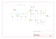
In other words, if you look at the AVCC schematic attached below, you could use an LT3045 3.3v regulator instead of the LT6655 if you want. Just don't use that LT3045 for anything else, it needs to stay very clean.
Depending on the state of your +-15v power supplies, you may find LM49720 or OPA1612 dual opamps to sound better. With a really low impedance +-15v supply most people find OPA1612 to be superior for both AVCC and for the output stage.
Since you are using LM317/LM337 +-15v regulators, you will probably get some low level power supply ripple intruding into your +-15 power. Using two sets of LM317/LM337 regulators in series can fix that. Each set of regulators needs need probably a 3v or more of headroom since they are not LDO types. Depending on your +-15v transformer and how much voltage it puts out before the existing LM317/LM337 regulators drop it down, you may have some wiggle room to work with.
Also, if using LM317/LM337 +-15v regulators, it sure helps to add some film capacitors filter caps from +15v to ground and from -15v to ground. Some people have started trying Kemet DC link film caps for that because they are low cost. I use about 100uf of film caps for each of the +-15v rails, which can get expensive. Maybe someone can post a message to let us know if the DC Link caps are working out okay.
We specifically don't recommend using LDO regulators for AVCC (with a possible exception for ADM7150, in at least some implementations). Opamp regulators are better for that. However, you could use one LT3045 regulator as a clean 3.3v reference voltage source and then use a dual opamp as a buffer to provide a separate 3.3v supply for each AVCC channel.
EDIT: Keep any wires from opamp outputs and opamp grounds very short when connecting AVCC power to the dac chip.
In other words, if you look at the AVCC schematic attached below, you could use an LT3045 3.3v regulator instead of the LT6655 if you want. Just don't use that LT3045 for anything else, it needs to stay very clean.
Depending on the state of your +-15v power supplies, you may find LM49720 or OPA1612 dual opamps to sound better. With a really low impedance +-15v supply most people find OPA1612 to be superior for both AVCC and for the output stage.
Since you are using LM317/LM337 +-15v regulators, you will probably get some low level power supply ripple intruding into your +-15 power. Using two sets of LM317/LM337 regulators in series can fix that. Each set of regulators needs need probably a 3v or more of headroom since they are not LDO types. Depending on your +-15v transformer and how much voltage it puts out before the existing LM317/LM337 regulators drop it down, you may have some wiggle room to work with.
Also, if using LM317/LM337 +-15v regulators, it sure helps to add some film capacitors filter caps from +15v to ground and from -15v to ground. Some people have started trying Kemet DC link film caps for that because they are low cost. I use about 100uf of film caps for each of the +-15v rails, which can get expensive. Maybe someone can post a message to let us know if the DC Link caps are working out okay.
Attachments
Last edited:
Thanks Mark.
What's the Vref used for? Also what's the difference in option E/F or is that simply a electrolytic/film personal choice? I should be able to put something together, I have a spare LM4562NA that should be more than sufficient for this task.
What's the Vref used for? Also what's the difference in option E/F or is that simply a electrolytic/film personal choice? I should be able to put something together, I have a spare LM4562NA that should be more than sufficient for this task.
@daminagt3,
We specifically don't recommend using LDO regulators for AVCC. Opamp regulators are better for that. However, you could use one LT3045 regulator as a clean 3.3v reference voltage source and then use a dual opamp as a buffer to supply a separate 3.3v supply for each AVCC channel.
In other words, if you look at the AVCC schematic attached below, you could use an LT3045 3.3v regulator instead of the LT6655 if you want. Just don't use that LT3045 for anything else, it needs to stay very clean.
Depending on the state of your +-15v power supplies, you may find LM49720 or OPA1612 dual opamps to sound better. With a really low impedance +-15v supply most people find OPA1612 to be superior for both AVCC and for the output stage.
Since you are using LM317/LM337 +-15v regulators, you will probably get some low level power supply ripple intruding into your +-15 power. Using two sets of LM317/LM337 regulators in series can fix that. Each set of regulators needs need probably a 3v or more of headroom since they are not LDO types. Depending on your +-15v transformer and how much voltage it puts out before the existing LM317/LM337 regulators drop it down, you may have some wiggle room to work with.
Also, if using LM317/LM337 +-15v regulators, it sure helps to add some film capacitors filter caps from +15v to ground and from -15v to ground. Some people have started trying Kemet DC link film caps for that because they are low cost. I use about 100uf of film caps for each of the +-15v rails, which can get expensive. Maybe someone can post a message to let us know if the DC Link caps are working out okay.
Thanks Mark.
What's the Vref used for? Also what's the difference in option E/F or is that simply a electrolytic/film personal choice?
Vref is there for if and when one gets around to building a proper 3-opamp output stage. The one-opamp output stage that comes with the dac board is there only because it is cheap. Unfortunately, it makes THD *much* worse than it should be. Recommended output stage instructions here: Dropbox - Output Stage Instructions.zip
Regarding the E/F opamp output caps, film caps were an experiment that worked okay, but not clear how much they really help. I think 47uf cheap electrolytics are probably fine for most users. The dac would need a lot of other improvements before film caps there matters much, if at all (I think).
Regarding 3.3v regulators, any regulators would be helpful to get the dac and clock loads separated out from each other and from the MCU regulator.
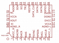
The clock and VCCA can be on the same regulator except maybe in the very best implementations. DVCC should be separate from VCCA and Clock. MCU can stay on the original regulator. Please see dac chip pinout diagram below. Note there are two VCCA pins, one on each side.
For best results with the DVCC, VCCA, & Clock loads, probably better to use a good LDO for each one of those if budget allows (3 regulators in total). LT3045 is used by some. I have used LT1763 mounted dead bug style under the bottom of the ground plane. Pics posted in thread, please let me know if any trouble finding what you are looking for.
At some point the clock should get an upgrade. We usually use 100MHz Crystek 575. Some people have reported satisfactory/good results with NDK NZ2520SD 80Mhz clocks (available from diyinhk for low cost). Either way, replacing clocks can be a bit tricky since there are four solder points for removal and again for replacement. A number of posts in this thread and some in another thread cover most of the details. Again, please ask if interested and any trouble finding things. Personally, I usually tend to do clock replacement very early in a project to get it out of the way.
After modding all power supplies and voltage regulation, replacing clock, and building output stage, the next thing I usually try to get people interested in doing is tweaking dac chip registers. Once that is pretty well understood, one could move on to phase-locked AK4137 clocking.
The more I think about AK4137 and what I have learned from clock division experiments leads me to suspect that a much simpler divider and perhaps a yet to be determined reclocker could possibly be an easy solution. One thing we don't know when running the dac at 100MHz and AK4137 at 25MHz is exactly when the best time for DSD signals to be stable for input by the dac for best resulting sound quality. When MCLK edges occur, when the dac itself indicates it wants to see DSD signal edges, and what relative timing results in best SQ is still less than fully sorted out. Probably, another set of experiments is in order. However, not sure I want to do them with modded dac #2. Maybe I will play around with another dac to see if I can finish settling the matter in a way that would be easy and low cost for prospective modders to implement. However, right now there is no pressure on me to work fast, since pretty much everyone stops working on the dacs when the prospect of register tweaking looms next.
Attachments
Last edited:
Hi Mark and all,
I finally got around to comparing my new Khadas tone board to my ec9038q2m board. They do sound a bit different in how they present music although they do have that ESS house sound. I used the Khadas using usb wasapi 32 bit vs coax wasapi 24 bit for my es9038q2m board. The Khadas is very impressive, nice clean and controlled, great imaging and nice soundstage, it sounded a bit more polite than my es9038 board, similar to my Subbu dac, but that may have been due to different filter choices. The es9038 sounded bigger than the Khadas, seemed to have a larger soundstage, imaging not as forward as the Khadas. With the Khadas the background instruments were a bit more restrained, with the ES9038 they were more apparent and in your face. The Khadas may have been a tad smoother, but it was hard to tell. The bottom line it is hard to choose a preference between these two. The Khadas is just a tiny little board and really handy and easily portable, certainly an faster and cheaper way to get good sound fast, but where is the diy fun in that. I still prefer the AK4490 over either, better vocals, more realistic decay on strings, hihats, piano, ect. But I could easily live with the Khadas or es9038. My next step will be to power up my output stage, if it doesn't smoke, I'll attempt to hook it up to my es9038 board.
Paul
Hi Paul,
If you are still using the stock output stage, it would be surprising to me if the modded dac could compete with ToneBoard in any way. All the mods we recommend help improve the sound, and the final step of getting the divided clock AK4137 timing just right is what takes it over the top to beat every dac it has been subjectively compared with so far, short of DAC-3. Of course, there are certainly other dacs that could beat the modded dac if only there were one of those other dacs here so we could try it. (Maybe that will change one of these days 🙂 )
The main point I would like to make at this time is that people buying some of the new low cost dacs that measure very well in the hopes of bypassing a lot of modding work and still ending up with a very good dac, are, IMHO, probably wasting time and money on those things. No way to get from one of those to something that could beat an Allo Katana equipped with good power supplies. And even Katana, very good as it is, cannot beat a *fully* modded dac like we work on here. All in IMHO, of course.
Hi Mark,
I was also surprised how well the es9038 board held up against the tone board. It wasn't so noticeably worse that you could immediately put your finger on it, unlike some nos DAC implementations that I've heard. I suppose you could say that the tone board was more accurate. But DACs are just entertainment machines after all, so for me at least choosing between accurate and entertaining can be tough. None are completely true to live music
I was also surprised how well the es9038 board held up against the tone board. It wasn't so noticeably worse that you could immediately put your finger on it, unlike some nos DAC implementations that I've heard. I suppose you could say that the tone board was more accurate. But DACs are just entertainment machines after all, so for me at least choosing between accurate and entertaining can be tough. None are completely true to live music
For me it is a little obscure, what you mean with that DAC battle, which one can beat what. All this is a way too subjective as discussed above imho. Obviously $$$$$$ is supposed to be better than $. I recommended ToneBoard and it is very good USB dac for less than 100USD out of the box. Nowadays it is available from Digikey as well. I listen to it while soldering other my projects, which indeed are time and money consuming.
H Paul,
Recording and reproduction of music is never completely true to live music. Actually, in some ways that is fortunate in the sense that it leaves open the possibility that recorded music can sound better than live music.
In fact, for almost any music other than recordings of classical music recorded with a single pair of condenser mics, most modern commercial recordings are made to sound better than live music ever could.
If what you hear on your hi-fi doesn't sound better than any live popular music concert, it just means your hi-fi is not reproducing what was recorded as accurately as you might find to your liking.
A big first step that can be done for pretty low cost is to make a pretty good dac. If making one isn't an option, then save up pennies for one would be my recommendation. Spending $100 or a few hundred dollars a pop for the latest good measuring dac(s) isn't going to get you there. Not ever, because they are not mod-able enough. Probably better to save that $100 or however much a few times and buy one Katana dac, then save up some more and buy a good power supply for it. It could likely give you several years of pretty good listening.
If you want even a bit better and if you would rather mod a dac, then don't stop too soon. People always stop before they get to the really good stuff. In that case, probably still better to buy Katana, and skip the other dac shopping by measured numbers alone and all the associated forum excitement that peaks and fades before long.
MHO, published measurements for dacs even if taken with fancy AP analyzers don't measure everything audible that could be measured, and what is measured doesn't completely correlate with how at least some humans hear, at least not in ways that we fully understand. Ultimately, measurements do matter, no doubt about that, but subjective listening tests matter too. Again and as usual, all the foregoing is IMHO.
-Mark
Hi Mark,
I understand where you are coming from. And I agree with most of what you say. That said I have never heard a recording capture a live piano, or human voice perfectly and I listen to a lot of live music True the venue can ruin a performance and modern recording techniques can really help. The difference is like using fresh or dried herbs in cooking, the complexity of the real thing always wins for me. I am a retired chem engineer, I do understand some of the technical challenges, but at this point 'I'm not looking for absolute perfection in a DAC, just something better than what I have. So far I still have more work to do
Paul
For me it is a little obscure, what you mean with that DAC battle,
eziitis,
What I mean subjectively, is that if you were here you virtually certainly would agree with everyone else who listens and decides what they prefer. They all independently come to the same conclusions, as the differences are not so subtle as to make it hard.
Unfortunately, you are not here, and we don't listen to same dacs, amps, and speakers so there is no way to correlate experiences. If we could agree to get the same headphones and build the same headphone amps, then we might at least have a chance to compare notes and see if we find each other's listening judgments consistent with our own.
For the sake of clarity, when I say one dac beats another, it means that trained and experienced listeners find no subjective disagreement about SQ rankings. There are no ties or disagreements between such listeners at the moment. At times there have been ties, or differences that are so close it is hard to be sure which sounds better, and when there are then we say so. We just don't have any that close at the moment, so one dac beating another is just a casual way of saying one dac is unanimously and unambiguously subjectively ranked as having better SQ than another as judged by trained and experienced listeners.
Of course, we always use DAC-3 as the standard listening reference. Without that or some equivalent reference, we could not be nearly as consistent and or reliable at subjective listening comparisons.
Last edited:
... I have never heard a recording capture a live piano, or human voice perfectly
Hi Paul.
I haven't heard that either. Certainly not from a PA system. Live acoustic music in a room is something that the ears and brain and hear in a way that no pair of mics can. As as easy experiment, a trick recording engineers use to approximate what a mic will pick pick up is to stick a finger in one ear and put the other ear where the mic will go. Just take a moment to try it, if you would.
...
See what a problem that creates? There is no perfect solution to it I have heard, although there have been various technical attempts at it.
Aside from that problem, most recorded music captures vocals and piano better you could hear live with one ear plugged up, and often better than with both ears. Depends on a lot of factors. Most pianos at live events are not in perfect (hopefully 'stretched') tune. Most vocalists don't sound that great dry, without some room reverb. Lots of other factors too that can make recorded music sound better.
However, one's memory of a live event may vary considerably from the reality of it. If we both went to the same live event and if it were not too loud to communicate, I'm sure we could find many shortcomings in the sound of live vocals and live piano that might not stick with you if you had not listened for them specifically and if you did not take written notes so you wouldn't forget later. Also, if it was loud during the performance, that could mask a lot of faults with the sound that one might easily hear on a recording later if played back at a lower volume level.
-Mark
+/-15 filter capacitors
Hi Mark & others,
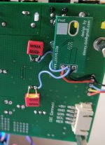
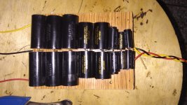
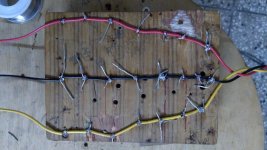
Finally finished assembling filtering caps for the main op amps power supply. The caps are from previous crossover builds detailed as below:
dayton audio grade(250v) 10uf 3+3
jantzen crosscap MKP(400v) 6.2uf 2+2
" 1.10 1+1
" .45 1+1
" .68 1+1
" .82 1+1
" .39 1+1
Total 91.68uf (45.84uf per line)
These filters and feeds the 4 1612 op amps, one avcc and 3 output stages from a 317/337 board.
My word! What a difference it makes. The sound has become so good that it matches or sometimes seem to surpass what comes to my headphones(using aune t1 mkII amp) for dsd, flacs and good quality youtube videos like vevo etc. Of course my rig and point of reference are modest. But considering that listening room has no room treatments, small, concrete, lots of outside noise and all kinds of wrong by acoustic standards, I find it hard to believe the sound I am hearing.
Thanks especially to Mark for his guidance and encouragement.
Regarding the clock divider, I am watching with interest. Right now, it seem too expensive for me. If am right, the evms for those cost $250 & $150.
Cheers,🙂
Kay.
Hi Mark & others,
Finally finished assembling filtering caps for the main op amps power supply. The caps are from previous crossover builds detailed as below:
dayton audio grade(250v) 10uf 3+3
jantzen crosscap MKP(400v) 6.2uf 2+2
" 1.10 1+1
" .45 1+1
" .68 1+1
" .82 1+1
" .39 1+1
Total 91.68uf (45.84uf per line)
These filters and feeds the 4 1612 op amps, one avcc and 3 output stages from a 317/337 board.
My word! What a difference it makes. The sound has become so good that it matches or sometimes seem to surpass what comes to my headphones(using aune t1 mkII amp) for dsd, flacs and good quality youtube videos like vevo etc. Of course my rig and point of reference are modest. But considering that listening room has no room treatments, small, concrete, lots of outside noise and all kinds of wrong by acoustic standards, I find it hard to believe the sound I am hearing.
Thanks especially to Mark for his guidance and encouragement.
Regarding the clock divider, I am watching with interest. Right now, it seem too expensive for me. If am right, the evms for those cost $250 & $150.
Cheers,🙂
Kay.
Attachments
... so one dac beating another is just a casual way of saying one dac is unanimously and unambiguously subjectively ranked as having better SQ than another as judged by trained and experienced listeners.
....
I see... but with all the respect why just not simply say, that me and friends of mine preferred sound of dac X over dac Y? it would be pretty fair and clear, wouldn't it?
I see... but with all the respect why just not simply say, that me and friends of mine preferred sound of dac X over dac Y? it would be pretty fair and clear, wouldn't it?
Actually, I don't think so. If only it were that simple. I believe that having a reference dac such as DAC-3 (or equivalent), and having particularly skilled listeners brings more objectivity to the judgments than merely to say, "my friends and I prefer X dac." Of course, that is my opinion, but it is what I believe and I stand by it. To whatever extent people here have found my advice on modding dacs and or answering their technical question to be accurate and helpful, I stand by the listening judgments as much as I stand by anything else I believe to be true. However, and to be very clear, all my beliefs are subject to revision in the light of new evidence. So, readers of my posts in this thread can take my advice and or recommendations as they wish. I try to get things right, and if I fail, then the failure is on me I will try to learn and do better in the future. That's all I can do.
- Home
- Source & Line
- Digital Line Level
- ES9038Q2M Board