typically ESS: lows and "musicality" a bit tiny. mine measures basically like reviewed one: Review and Measurements of WesionTEK Khadas Tone Board DAC | Audio Science Review (ASR) Forum
parts used are "cellphone" targeted. good smd skills and microscope indispensable for modding.
anyway, the sound is really clean, and one would need to spend at least twice as much to get to this level with the board discussed.
having said that, it is on the "boring" side, because the happy owner will miss all the exciting hassle to make it better 🙂))
Attachments
Last edited:
These boards (the original 1.07) are proving a little troublesome. Neither will get a permanent i2s lock from my miniDSP 2x4HD, a little flash for a second as the miniDSP boots up then it's off. My PCM5122 RPi boards had no such issues, is this a input impedance issue?
Also, has anyone checked the provenance of the components ie. caps, regs etc? I have 7805 on one board that's getting extremely hot, whilst the other is just warm to touch.
Also, has anyone checked the provenance of the components ie. caps, regs etc? I have 7805 on one board that's getting extremely hot, whilst the other is just warm to touch.
@damiangt3
Most likely the components are low cost. You might try some troubleshooting, or just measure the hot 7805 temp and see if it is within limits. Could be you have a faulty component. If so, maybe quicker and easier to fix it vs sending it back to China. Or maybe the issue can be safely ignored if 7805 device temp is within data sheet specs.
If I2S doesn't work you might check the signals with a scope, and also check that miniDSP is actually sending I2S rather than LJ or RJ PCM.
You would also be very welcome to post a pic showing how its its hooked up. Also, IIRC, for those boards both J1 and J2 have to be removed to select I2S. If there is a display or not, then at the minimum do not install J1 and J2 at the same time or the system will stop.
Last edited:
Thanks for the tip, just bought one. I'll compare it to my model es9038q2m when it arrives.
Paul,
If you think you might want to mod the ES9038Q2M board that you have now, but are put off by the prospect of building an output stage, Iancanada has some finished output stage boards that should work for only $35. DocumentDownload/RPiDacHAT/IVboards/IVSTD at master * iancanada/DocumentDownload * GitHub
Don't know if any are still in stock right now. If not, he could put one on the back order list. Its not exactly the same output stage we built here, but it should be similar enough to use. Don't know why someone shouldn't give it a try. I would only recommend to try to solder its ground plane directly to the dac board ground plane if possible. Maybe some copper foil could help with that.
Hi Mark,
I built the output stage posted here point to point but haven't tried it out yet. I was sidetracked when I wrecked my first board. Now that everything is back together and working I'll give it a try, but my confidence that it will function isn't very high, it looks like a real mess. I did check it over carefully for mistakes and didn't find anything obvious., But then again I'm no EE. Maybe I'll put power to it first and if it doesn't go up in a puff of smoke I'll go through the trouble of modding the board and try to squeeze it into my case. But first I want to audition it against the Khadas board before I take the chance of breaking it again.
Paul
Sorry, my bad. Ignore above.
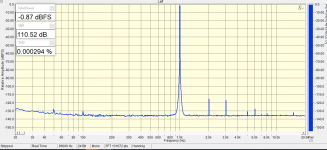
I did not power the op amp dual 15v when I did the test. I am sure it will be correct when that is done.
Again, its even worse! With the opamp opa1612 powered with 15+/-, I get 0.14v avcc and 0.07v vref! What could be the problem??
Any suggestions?
Sorry again, for the last time I hope.
It seems my dmv connection & or circuit connection is not stable.
I finally could get to the correct reading ie. 3.3v for avcc and 1.65 for vrefs. Yay!
Cheers,
Kay
Hi Kay,
Good to see you made an AVCC board and got it working! Also, great that you were willing to try using SMD components. (I think that would have been easier for our output stage to use SMD too, but at the time people said they wanted to use through hole components so that is the way it ended up.)
Cheers,
Mark
Hi Mark,
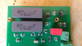
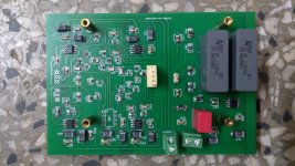
I did both avcc and output stage on the same board with differential output. Pics attached below.
Just finished so did not have the heart to attach them yet, so still don't know if it works. I followed the schematic you(and Mr. Slim) did for both OP and differential. As it is my first pcb design, many things I would have done differently if I design it now. For one I forgot to put ground line connections for avcc and output.
I still also have to modify the green board v1.07. My blue board and another green board was destroyed because of silly mistakes.
I tried connecting the both i2c and i2s to the board using rpi, but could not get it working as per eslei's instruction using volumio driver and plugin.
I am now using xmos board with my pc, with ak4137 upsampling board in-between. Still learning how to set up the up-sampler. Got it working in pcm mode with jumper connected on D/P. Would appreciate it if you could advise me on the settings you did.
Regards,
Kay.
Attachments
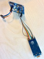
Hi Mark,
Its the standard version of this one: AK4137 I2S/DSD Sample Rate Conversion Board Supports PCM/DSD Interchange Supports DOP Input for hifi amplificatore-in Amplifier from Consumer Electronics on Aliexpress.com | Alibaba Group
Kay
Its the standard version of this one: AK4137 I2S/DSD Sample Rate Conversion Board Supports PCM/DSD Interchange Supports DOP Input for hifi amplificatore-in Amplifier from Consumer Electronics on Aliexpress.com | Alibaba Group
Kay
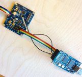
Actually, I posted picture before of how to wire it up. The AK4137 board should have some extra ground pins added (yellow color in the pictures) and the I2S output connector should be replaced with high quality gold flashed or gold plated pins, or ribbon cable wires should be soldered to the bottom of the pins on the ground plane side of the AK4137 board to minimize jitter. Any connectors at the ends of ribbon cables should have high quality gold connections. The D/P jumper should be removed to prevent damage to any boards, and the wiring to XMOS or Amanero board should be as shown below. At the dac end of the ribbon cable, either high quality gold pin headers should be used for I2S and DSD to help minimize jitter, or the ribbon cables should be soldered to the dac board. Try to keep the I2S cable between the AK4137 output and the dac board input as short as possible. A few CM is okay. (If you open the pictures then click on white X in the lower left hand corner they will blow up to full size so you can see the wiring better, or you can right click and choose to download the pics.)
Attachments

Last edited:
@damiangt3
Most likely the components are low cost. You might try some troubleshooting, or just measure the hot 7805 temp and see if it is within limits. Could be you have a faulty component. If so, maybe quicker and easier to fix it vs sending it back to China. Or maybe the issue can be safely ignored if 7805 device temp is within data sheet specs.
If I2S doesn't work you might check the signals with a scope, and also check that miniDSP is actually sending I2S rather than LJ or RJ PCM.
You would also be very welcome to post a pic showing how its its hooked up. Also, IIRC, for those boards both J1 and J2 have to be removed to select I2S. If there is a display or not, then at the minimum do not install J1 and J2 at the same time or the system will stop.
Hi Mark, thanks again.
I removed J1/2 so no issues with that. Is there anything that needs to be connected to the 5v line?
The MiniDSP works with my two PCM5122 boards via I2S.
Hi damiangt3,
The 5v pin located with the I2S pins shouldn't be needed, at least so long as the dac boards are powered from a +-12v supply with sufficient current capability for the combined load. Have you checked the voltages on the dac boards with a meter? Everything look okay? IIRC, you said one regulator was getting pretty warm (which might actually be normal, so maybe good to check both boards).
Also, I wonder if there might be any other way you can test the boards to verify they are working other than with miniDSP I2S? Maybe SPDIF or TOSLINK? How about some type of XMOS, Amaneraro, or CM6631A USB to I2S interface? Having two boards not working seems quite suspicious, as it is pretty rare IME for even one board to arrive dead. Don't know a single dead board was ever reported in this thread where it didn't turn out to be some configuration issue. Of course, there could always be a first time. Question would be how to troubleshoot given whatever resources you may have on hand. Did you already try connecting them only one at a time?
Last edited:
Hi Mark,
Both boards work perfectly well when 'fed' with a SPDIF source so I have no concerns on the boards themselves.
My PCM5122 boards work with the MiniDSP when sharing the BCLK, LRCK, GND the DATA line being attached to the respective pin on the MiniDSP.
It's all very odd! I do have a Teradak X2 that I could output a i2s signal from that might help with diagnosing this issue.
Trying the Teradak X2 sounds like a good idea to me. Other than that, I can only suspect the possibility that the PCM format being sent out by miniDigi isn't I2S. The other dacs you had working with miniDigi can work with more than I2S PCM format and so can ES9038Q2M, but for the latter the settings are only accessible in the dac registers, not through the MCU. If not that, then maybe the leads are swapped, or some other weird problem. Example of a good reason to keep some kind of oscilloscope around. There are cheap ones on ebay now that can work up to 20MHz or so. Rather low bandwidth for some dac work and possibly for some oscillating analog amplifiers, but still good enough for most audio work.
- Home
- Source & Line
- Digital Line Level
- ES9038Q2M Board