Hi Mark,
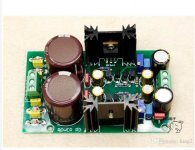
I've built many psu's before, but decided to try out a quick and cheaper alternative for this project. For about 20 bucks delivered I got a Chinese Kubota psu off of ebay, a lot cheaper that I could put one together for. I guess you get what you pay for. It is designed to deliver 500 ma, using a 10 va transformer should be enough for this dac. It worked fine for a while, no rail sag, no excessive heat. Now it runs very very hot even with no load, and with load the rails sag, the trafo is also getting warm. At this point I'm afraid to use it. From what I've been able to read on the web it is a constant current type of psu similar to a shunt. I'm guessing some of the transistors failed dumping a lot of current to ground. Attached is a schematic that I found and a pic of the psu. I can't guarantee the board I bought matched the schematic, there was none available at the sellers site. I have some known high quality psu boards from Salas that I'm going to use to upgrade my better dacs. If the LT1083 psu that I ordered to replace this piece of junk craps out I'll recycle an old psu from my upgraded dacs.
Paul
Attachments
Paul,
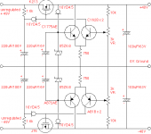
The the pairs of two bipolar transistors with the emitters tied together are a differential pairs. One transistor base connects to a zener diode reference voltage (the zener is fed current by a constant current diode which are shown with the flat line and circle symbol. The zener voltage is also filtered of noise by a parallel elelctrolytic cap). The other transistor of each differential pair connects to pot wiper that samples the power supply output voltage. Depending on the pot setting, the differential pair should try to create an error signal (if their bases are at two slightly different voltages, that's a slight error in the desired output voltage). The error signal from the pair drives the gate of a MOSFET pass transistor. The other constant current diode at the gate of the MOSFET is connected to filtered power on one end, and the other end that connects to the MOSFET gate supplies collector current for one of the differential pair transistors. Using a current diode for that rather than a resistor for that helps to make the power supply regulation better by resulting in increased feedback loop gain of the differential error amplifier.
Hope the above helps to understand how the circuit is supposed to work. You can check with a voltmeter what happens if you connect a resistive load and turn the adjustment pots. The 6.8v zener reference voltages should remain steady, and the differential pair error amplifier should create a signal to turn on the MOSFET gate just enough to keep the output voltage in regulation.
EDIT: Also, the BJT differential pair transistors can probably checked in the circuit to make sure the PN junctions are intact and dropping around maybe .4v to .7v in the forward direction, and pretty much high impedance in the other direction. Many DVMs have a diode check function that can be used for that rough test. The transistor junction diode drops should be consistent for each pair of differential transistors. For the transistors with their bases tied to the zener references, the zeners will be forward biased when checking the reverse drop of that transistor emitter-base junction, so you may see some forward diode drop from the zener which should not create alarm as it is kind of expected. Some of what you would see would depend on the 750-ohm emitter resistor which would effectively be in series with the forward biased zener if measuring at the transistor base-emitter. The constant current diodes behave a little differently. Inside they are much like a FET with the gate tied to the source which makes them act like a sort-of imperfect constant current source (Idss).
Last edited:
Any ideas why the Topping D50 uses unsymmetrical voltage divider for Vref of I/V op amps?
its only 0.8V
its only 0.8V
laserscrape,
diyinhk does something similar with their low cost, mostly unpopulated ES9028PRO board. I don't know for sure, but I would assume they found by way of testing that it sounded better or measured better in their particular implementation. Perhaps it helped with H2 distortion without having to adjust harmonic compensation registers for each and every dac, and then burn the values into nonvolatile memory somewhere. Making that adjustment can require time consuming manual labor, and therefore likely a large percentage of manufacturing costs for a low cost dac.
However, adjusting harmonic distortion compensation is probably better because then both H2 and H3 can be adjusted, and the I/V stage opamps can run class-A and therefore free of opamp output stage crossover distortion.
Class A operation arises automatically if we adjust the IV feedback resistor for about 3v peak to peak voltage swing at full dac output. The way that works is because the non-inverting IV opamp input is connected to Vref = AVCC/2. If AVCC = 3.3v then Vref = 1.65v. With 3v peak to peak swing the maximum IV opamp output voltage in the positive direction will be 1.5v + 1.65v since that is = Vswing/2 + Vref. In the negative direction the opamp output can go as low as -1.5v + 1.65v. Even in the most negative case, it never goes below (opamp presumed) ground = [V(+rail) - V(-rail)]/2 , where opamp output crossover would occur (where opamp-presumed ground = the average rail voltage, half way between the two +-15v rails as referenced to ground, at least for an opamp without a ground sense or common-mode reference pin). That's how I look at it anyway.
Last edited:
... ~1.5v peak to peak out of the 3v peak to peak maximum swing?
The D50 has max 2V output, should have clarified that 🙄
Just curious, so that I understand correctly you measured peak to peak swing at 0dBFS at the IV opamp outputs = 2v, and also measured Vref = +.8v? Just asking because sometimes dac specifications may have some numbers measured differently, such as perhaps:
*Both single-ended and balanced 2v outputs available*
Thank you in advance for you patience with me.
*Both single-ended and balanced 2v outputs available*
Thank you in advance for you patience with me.
just quoting this post on ASRJust curious, so that I understand correctly you measured peak to peak swing at 0dBFS at the IV opamp outputs = 2v, and also measured Vref = +.8v? Just asking because sometimes dac specifications may have some numbers measured differently, such as perhaps:
*Both single-ended and balanced 2v outputs available*
Thank you in advance for you patience with me.
absolutely no need to thank me 🙂
oh and yeah, I measure with multimeter the voltage between the voltage divider (if it wasnt already evident from 10K and 3.3K resistor)
Last edited:
Windows or Other OS Sound Device Configuration
Can't believe I didn't post about this before. At least, I couldn't find it.
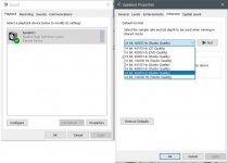
Okay, here goes: Windows and most modern computer OS audio systems will do real time poor sound quality SRC on your audio before playing the audio and they don't tell you they are doing it. Further, it is tricky to make them not do it. Please see the picture attached below.
It shows the windows sound device configuration in the windows control panel. I clicked on the one sound device in this computer then with it selected clicked the properties button in the lower right part of the left pane. At the top of the left pane you can see the sound device has a green check mark indicating it is the default device. There are actually two default devices at it is both, one for sound playback and one default for communication. In the right pane the properties box for the sound device is open. In the advance tab as shown there is a setting sample rate and bit-depth. There are also some check boxes to allow exclusive mode and configure it. They should be checked but it won't help. If a device is the default device then windows will always manage it via the windows sound engine and its poor sound quality SRC, Windows will do the same thing if the device is not the default device, but the sample rate and bit dept you have set are not exactly the same as the music file you are playing. Windows will also take control even if the sound device has ASIO drivers if is a default device.
Here is the only reliable fix I know of to make sound quality as it should be in windows. (macs do similar, and some linux might too): You must have at least two sound devices to choose from, set the one you don't want to use for music playback to the default for sound and for communications (it should be the only device with a green check mark). For the device you do want to use either set the default sample rate and bit depth to exactly match the music file you want to play next, or the best way is to make sure the device you will use has ASIO drivers or at least that it works with the free ASIOforALL driver. Then install foobar2000 as your music playback app (or use a paid app that support ASIO). Foobar can use ASIO but you have to download and install the optional ASIO component. Once it is installed, restart foobar and in the configuration options 'output settings' tab there is a drop down menu to select the sound device. Select the ASIO driver for the sound device you want to use (and that isn't the windows default). You may need to close and reopen foobar to make sure the setting sticks. There will be another ASIO page option below the output configuration page option. You don't need to configure that, it is for custom mapping of the ASIO output channels. Now when you play music, foobar can and will automatically use ASIO to configure the sound device to play using the exact same sample rate and bit depth as the file, so no crappy SRC will be required or used.
You will also need to turn down the master volume level in windows for the device you will use. You can do that in the control panel device properties 'levels' tab, or using the sound volume control slider in the lower right hand area of the desktop task bar. To prevent intersample overs in AK4137 you must turn down the master slider for the sound device to about -4dBFS (if a Sabre dac, the its hardware volume control also needs to be turned down to prevent intersample overs in the ASRC stage, or the Windows master slider must be turned down enough to avoid overs in both AK4137 and the dac ASRC, about -7dBFS to to -8dBFS should be the master level setting so as to minimize distortion). If you right click to the on the slider knob or the little speaker icon in the control panel device properties level tab, you can change the display from percent to dB which makes it easier to apply the correct level adjustment. From then on, only use the foobar volume slider or the dac hardware volume control to adjust playback volume, you can also use a volume pot in a preamp or power amp.
Can't believe I didn't post about this before. At least, I couldn't find it.
Okay, here goes: Windows and most modern computer OS audio systems will do real time poor sound quality SRC on your audio before playing the audio and they don't tell you they are doing it. Further, it is tricky to make them not do it. Please see the picture attached below.
It shows the windows sound device configuration in the windows control panel. I clicked on the one sound device in this computer then with it selected clicked the properties button in the lower right part of the left pane. At the top of the left pane you can see the sound device has a green check mark indicating it is the default device. There are actually two default devices at it is both, one for sound playback and one default for communication. In the right pane the properties box for the sound device is open. In the advance tab as shown there is a setting sample rate and bit-depth. There are also some check boxes to allow exclusive mode and configure it. They should be checked but it won't help. If a device is the default device then windows will always manage it via the windows sound engine and its poor sound quality SRC, Windows will do the same thing if the device is not the default device, but the sample rate and bit dept you have set are not exactly the same as the music file you are playing. Windows will also take control even if the sound device has ASIO drivers if is a default device.
Here is the only reliable fix I know of to make sound quality as it should be in windows. (macs do similar, and some linux might too): You must have at least two sound devices to choose from, set the one you don't want to use for music playback to the default for sound and for communications (it should be the only device with a green check mark). For the device you do want to use either set the default sample rate and bit depth to exactly match the music file you want to play next, or the best way is to make sure the device you will use has ASIO drivers or at least that it works with the free ASIOforALL driver. Then install foobar2000 as your music playback app (or use a paid app that support ASIO). Foobar can use ASIO but you have to download and install the optional ASIO component. Once it is installed, restart foobar and in the configuration options 'output settings' tab there is a drop down menu to select the sound device. Select the ASIO driver for the sound device you want to use (and that isn't the windows default). You may need to close and reopen foobar to make sure the setting sticks. There will be another ASIO page option below the output configuration page option. You don't need to configure that, it is for custom mapping of the ASIO output channels. Now when you play music, foobar can and will automatically use ASIO to configure the sound device to play using the exact same sample rate and bit depth as the file, so no crappy SRC will be required or used.
You will also need to turn down the master volume level in windows for the device you will use. You can do that in the control panel device properties 'levels' tab, or using the sound volume control slider in the lower right hand area of the desktop task bar. To prevent intersample overs in AK4137 you must turn down the master slider for the sound device to about -4dBFS (if a Sabre dac, the its hardware volume control also needs to be turned down to prevent intersample overs in the ASRC stage, or the Windows master slider must be turned down enough to avoid overs in both AK4137 and the dac ASRC, about -7dBFS to to -8dBFS should be the master level setting so as to minimize distortion). If you right click to the on the slider knob or the little speaker icon in the control panel device properties level tab, you can change the display from percent to dB which makes it easier to apply the correct level adjustment. From then on, only use the foobar volume slider or the dac hardware volume control to adjust playback volume, you can also use a volume pot in a preamp or power amp.
Attachments
Last edited:
+1 Mark
Yep, W10 (and Macs) do that for the sound... and also for the pictures.
I had to fiddle around as you said with 2 devices to get close a sound from my PC reading my CDs than from my still cherisched CD Player (for serious listenings) and it took me a lot of time and effort to get it right for the pictures, splitting sound and image and then processing images as it should through special softwares (MadVR as platform & then dedicated stuff).
And despite all this, at each majour update, W10 tends to force its settings and ruin all what I did, activating again per defauts its... s*$$y systems and also affecting the output resolution (which leaves then the beamer doing upscaling job, not the best thing)
Anyway, digressing, point is indeed most people listen to MS and Mac sound and not to real music without knowing it
Have a nice WE
Claude
@Markw4 On the other topic of FPGA interpolation, it seems like it'd be very reasonable to implement a good quadratic interpolator that behaves reasonably well near the Nyquist frequency. Especially with Verilog code examples being available from ZipCPU for free on github.
I will take a look at the ZipCPU and the quadratic interpolator.
By the way, I did some checking and it looks like Sharc SC589 can support FS of 384KHz for I2S using a SPORT Clock frequency of 24.576 MHz. That's about the maximum.
By the way, I did some checking and it looks like Sharc SC589 can support FS of 384KHz for I2S using a SPORT Clock frequency of 24.576 MHz. That's about the maximum.
I will take a look at the ZipCPU and the quadratic interpolator.
By the way, I did some checking and it looks like Sharc SC589 can support FS of 384KHz for I2S using a SPORT Clock frequency of 24.576 MHz. That's about the maximum.
Yeah the interpolating should be done on a FPGA. I'm sold now. Here's the original article about implementing interpolation on the FPGA that I found after finding the code first: Quadratic fits are entirely inappropriate for DSP
Dan Gisselquest has some fantastic articles on his blog that are really valuable.
I was originally thinking to do interpolating and FIR filtering on the Sharc, but now I'm thinking that it might be worth it to try implementing interpolating and high-order FIR filtering both on (separate) FPGAs instead. I'd need to give some thought on how I'd want to structure the whole thing. I'd also want to do a FIFO reclock on output before the DAC stage. Although that might not be necessary depending on how it's all set up, since you'd figure it'd be quantized against the clock during interpolation.
Actually, as it turns out there are some interesting papers on quadratic interpolation filtering for audio DSP. However, some of the methods have been modified in rather sophisticated ways to get the best results. With enough processing power is possible to get very impressive SNR, but nothing I have seen shows an analysis of distortion.
Regarding ZipCPU, I'm guessing its not super powerful, but didn't check yet.
For FPGA, I have been thinking about it for awhile, and have some ideas about how to do it. That includes clocking and buffering of I/O. Haven't read all the clocking resource, arithmetic slice, etc., configuration and programming manuals yet, and that is not to mention getting up to speed on VHDL and or Verilog. Then there is Vivido to learn.
If you are serious I would recommend getting the same FPGA board I have for development work. The clock speed isn't that fast, but even getting an upsampling filter working for 24/44.1 could demonstrate enough to justify getting or making boads with higher speed grade parts and or more expensive model FPGAs with more slices. One of the issues is whether time domain multiplexing of the arithmetic slices will be needed. There is also the issue about how to handle left/right channel data. The same slices can be used for both channels by swapping out, saving and restoring samples needed for when calculations for one channel have to be interrupted and resumed. Lots of stuff like that to think about before going too far.
One really good thing about the FPGA board I have is there are some demo programs including source code, and one of them is for a 24-bit I2S volume control. It might help a lot to take a look at how that works.
I have printed out a big pile of manuals to read. It takes three manuals at once to understand the arithmetic slice and the VHDL to program and use it. There are two macro library manuals, one in VHDL and the other in Schematic format, then there is an arithmetic slice manual that describes how the thing works. Between three manuals spread out at once on the kitchen table, it is possible to make some headway.
So far I have only run one of the sample programs through the whole process of simulation, constraint definitions, understanding the VHDL, etc., all the way to writing the binary to the FPGA and observing it operating properly.
Next thing is I have to get the computer I want to run all that on reconfigured to run Ubuntu and Windows 10 (since some apps may only run on one or the other), and maybe CentOS too. Problem is trying to keep the boot loader for one OS from trying to take over control of booting all the previously installed OS's. I don't want that in case I have to reload any OS. if I nuke one, I risk nuking the whole computer. So, I am installing OS's with only one disk drive in the computer at a time. I will use the bios to select boot disks.
Last edited:
- Home
- Source & Line
- Digital Line Level
- ES9038Q2M Board