About 9 months ago actually. I think I was the first top point this thing out.
AckoDAC based on ES9038PRO
What actually makes difference with series-shunt topology is:
"Nazar`s regulator", variants - diyAudio
Here is one of its practical implementation:
TPA6120A HPA for HD800(回路図編): アナログ回路のおもちゃ箱
Oh dear, I'd better start saving
Hard to tell what it sounds like from the pictures. Before you spend your hard earned money, I would at least recommend reading most of the blog posts over at Benchmark Media. Their engineer, John Siau, also has posted at various audio websites if you search around. If you do some of that type of homework, you might be in a much better position to ask more technical questions of dac manufacturers rather than relying on pictures and advertising blurbs. At least you can decide what you think is important after maybe having your thinking on the subject stimulated a little.
Before you spend your hard earned money, I would at least recommend reading most of the blog posts over at Benchmark Media. Their engineer, John Siau
Thank you thats very useful.
you might be in a much better position to ask more technical questions of dac manufacturers
To be honest, there's not much to them, the chassis/main PCB has all the upgrade hard work done - seperate PSU's for each section, plus automatic configuration for dual mono, I think the I/V's based on a D1. looks like a good starting point, aparently there are no upgrades for the pro series - already done, he hasn't met me.
If I bought, I would want to know some of the finer details first. It would be nice to see a schematic first

I've been trying to find the time to finish development of a super shunt regulator, similar to the store Jung/Didden series reg; which is intended to power (an idea at the moment) a high current (1A per channel) I/V, the idea grew from a cross between the D1 and CEN but using current mirrors. The shunt can be easily adapted to replace any of the various PSU's.
It'll probably look like a dogs dinner by the time I'm finished 😀
Oh dear, I'd better start saving
using ES9038pro in 2ch mode is somehow very problematic. what one can do with nearly 50mA output? if your aim is still at some point get a good sound out of it, then perhaps you should look towards TP Mercury I/V. but then what's the point to mess with a cheap Chinese board if TP Buffalo is much better? and at the end of the day, one may find out that following this route made savings both financial and emotional...
actually, the link was provided to show that ESS reg does not make miracles ...
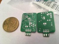
in contrast, one can try to implement serial-shunt concept with discrete parts.
Attachments
using ES9038pro in 2ch mode is somehow very problematic. what one can do with nearly 50mA output?
If I were designing with the chip I'd stick it directly into a 1:20 step-up transformer. Its one good way to put a low impedance load on the DAC while the I/V stage can afford to be higher input impedance.
Personally, I would rather not worry about what to do with big output current until I figure out how to make a Q2M sound as good as possible when operating as a general purpose dac, not only a hat (although that use is perfectly fine, but there are other use cases that need a good dac too). Until I can solve that set of problems satisfactorily, why add in yet another problem to puzzle over?
When I see nice shiny dacs that are all output stages and power supplies, I do actually wonder how good they can sound. Not going to buy one to find out though.
When I see nice shiny dacs that are all output stages and power supplies, I do actually wonder how good they can sound. Not going to buy one to find out though.
Last edited:
Personally, I would rather not worry about what to do with big output current
Granted that is an extra problem that needs to be solved; but the I/V is an area where large sonic benifits can be gained.
Agreed, all the other issues need to be addressed too; excluding the PSU's, and adding a low phase clock, there isn't much left to mod? I haven't seen or herd anyone mention the I2C side on these DACs, I'll have to dig a bit, read the FIFO thread etc.
When I see nice shiny dacs that are all output stages and power supplies, I do actually wonder how good they can sound. Not going to buy one to find out though.
Everything starts at the power supply, if it's compromised, so will everything else.
FIFO is likely to introduce an unacceptable delay in a general purpose dac. Upsampling can solve the problem, but the way some commercial dacs are doing it requires using presumably decent clocks at 27MHz, and 50MHz, and one other frequency. Don't want to use common audio clock frequencies for those to avoid idle tones. Also, part of the solution involves doing interpolation filtering and volume control in a gate array, such as Spartan 6.
I don't see the same clocks the commercial guys seems to be using at Mouser or Digikey. I haven't worked out the Spartan 6, only recently started looking into it. Getting the right development tools together on a low budget might be difficult.
At least using AK4137 and tweaking dac chip DPLL bandwidth seems to be a way worth exploring more for part of it, maybe enough for diy. But, still problems to solve there.
When I looked at the Acko DAC he told me that the DAC runs DSD material rock solid on lowest DPLL setting so he's doing something right. It was just too expensive for me...
When I looked at the Acko DAC he told me that the DAC runs DSD material rock solid on lowest DPLL setting so he's doing something right. It was just too expensive for me...
It would be interesting to know how that particular topic happened to come up.
However, its seems pretty clear the technology exists at some cost. There is a question about doing it at low cost, maybe with a 2-layer board, and with readily available parts obtainable in small quantities.
Also, easier with FIFO and master mode kind of approaches, but those things tend to be most applicable to special purpose dacs, rather than general purpose dacs.
In addition, having it rock solid at minimum DPLL setting, and sounding better than at any other DPLL setting, could be two different things.
Lots of unknowns there so far. Maybe more info will come in. Interesting stuff, for sure.
Time for me to get back to work on dacs today.
I played Katana for a bit as I had it last time to remind myself of the sound with isolator, 'thd' output stage, and modest linear supplies for +-15v and 5v rails.
Also, checked where I left the modded dac. It was still as I left it a few days ago running stable with DPLL at 6 out of 10.
In initial listening I preferred the sound of the modded dac, as it was less grainy than the sound of Katana. However, with the modded dac DPLL set to 6 out of 10, Katana had better audibility of low level reverb tails.
I then connected up some 10,000uf, .053 ohm ESR electrolytics to the Katana +-15v external linear supply. There was not as much change as I was kind of expecting, still grainy compared to the modded dac. I suspect that if I removed the bank of film caps from the modded dac and transferred them to Katana that might help more. The film caps are on the modded dac +-15v rails and are about 110uf per rail. Those may provide lower impedance and less DA ladder network sound than with electrolytics alone. Don't know til I try it if it will sound better. If it does sound better, exactly what the technical differences between the electrolytics and film caps are would have to later determined. I can speculate about possible reasons, but couldn't say for sure without more work. In any case, that experiment might have to wait, as I am not ready to remove the film caps from the modded dac yet.
Then added same type of 10,000uf cap to Katana 5v rail. Did not expect much if any difference since there is already a super cap and electrolytics on that rail internal to Katana. Just tried it to make sure, and, as expected, no audible difference to me.
Summary at this point is that neither dac, Katana or modded dac can equal or beat the other in every respect with any reliability. My preference for the two dacs in a stable configuration goes to the modded dac at this time as I prefer the lack of grain to the extra low level detail. However, I am not personally satisfied with the modded dac sound in that state. It is very good, but hopefully we can get it a little better. Just have to see how it turns out.
Also, as cdsgames suggested a few posts up, he would be happy for me to try modding Katana to see if I can make it any better. I wonder about that too, but I have to focus my efforts mostly on one thing at a time, and my commitment to the diy dac modders to see what I might be able to do about DPLL bandwidth setting stability will have to come first, at least for awhile. If I find myself stuck on that, I might switch to something else while I let the DPLL thing simmer on the back burner. Again, just have to see.
Last edited:
FIFO is likely to introduce an unacceptable delay in a general purpose dac. Upsampling can solve the problem, but the way some commercial dacs are doing it requires using presumably decent clocks at 27MHz, and 50MHz, and one other frequency. Don't want to use common audio clock frequencies for those to avoid idle tones. Also, part of the solution involves doing interpolation filtering and volume control in a gate array, such as Spartan 6.
I don't see the same clocks the commercial guys seems to be using at Mouser or Digikey. I haven't worked out the Spartan 6, only recently started looking into it. Getting the right development tools together on a low budget might be difficult.
At least using AK4137 and tweaking dac chip DPLL bandwidth seems to be a way worth exploring more for part of it, maybe enough for diy. But, still problems to solve there.
Mark,
Are you using SPDIF or USB as a source to feed AK4137 board, if the former what is receiver chip?
Also do you know what jitter rejection corner frequencies coincide with various DPLL settings?
This is all about LF jitter rejection, if you could come up with some numbers
it would would make the path forward clearer.
Sadly no details WRT jitter rejection on 4137 are available. It may actually be quite poor.
Terry
Mark,
Are you using SPDIF or USB as a source to feed AK4137 board..
I have used both. The more expensive model AK4137 board sold on ebay and aliexpress works either way, or with TOSLINK. I think it just uses the common AK serial audio receiver chip, although its not easy for me to read the numbers on it right now.
Also, I have not seen any detailed specs on the AK parts that would help me know how good they are at attenuating jitter. In addition, the particular jitter behavior of clocks, SRC chips, incoming data, etc., and how the dac may respond to them may depend on things about the jitter we don't know. Is it random, deterministic, some mix of both, what are the particular details of one or other, etc., are all things very uncertain to me. All I can do is report my experiments, observations, and or opinions as I do and it may be up to others if they want to investigate in more detail.
Yes it's somewhat of a minefield.
What sounds better or more transparent, the SPDIF or USB? Obviously
given same source material.
USB *should sound better if it's done right. It really is worth running the
DAC synchronously, ie; USB / I2S, internal ASRC disabled, to see where you are at.
That would answer a lot of questions. Most SPDIF have poor jitter rejection
at low frequencies so it then loads the job on to the 4137 - which also may
be poor, we don't know, then it's on to the DAC and it's DPLL settings.
Also, have you tried ADA4898 for I-V yet or are you still holding out because
data sheet looks (in some ways) bad? These are very god opamps. If you do
a bit of searching most people find them superior to the ones you have used.
T
Also, have you tried ADA4898 for I-V yet or are you still holding out because
data sheet looks (in some ways) bad? These are very god opamps. If you do
a bit of searching most people find them superior to the ones you have used.
Now that I have a dac with sockets in the output stage it might be possible to roll opamps. However, I don't have any of those in stock, and I have my own ideas about what I want to work on next. If I was dissatisfied with the output stage sound then I might have more interest.
Terry, you have so many ideas you would like to try and things to test, why don't you join in with us and mod your own dac like we are doing? If you catch up with where we are now, you could satisfy your curiosity and maybe even have some extra time to work on trying things I would like to suggest. 🙂
Could someone explain pins:
24-SDA
23-SCL
21-RESTB
The microcontroller in my Topping D50 that controls many things is muting/disabling the DAC when using an IS2 input from an external USB interface, I assume the controller detects a USB data input from internal interface and unmutes/enables accordingly.
looking at a simpler 9038q2m circuit that doesnt use a multilayered PCB I can see these 3 pins are connected to a microcontroller, so far this only guide I have to figuring out how to disable or bypass the mute.
Could someone explain pins:
24-SDA
23-SCL
21-RESTB
SDA and SCL are I2C bus pins to communicate with dac chip registers.
RESTB is to reset the dac chip to defaults.
Most likely your output is muted because something not configured correctly for it to obtain a LOCK on the input signal. For one thing, there are three possible versions of what we commonly refer to as I2S. There is 'Left Justified,' Right Justified,' and 'Philips I2S.' if one of those things is configured inappropriately then I2S LOCK will fail. If you want to completely take over control of the dac chip, then you might be able to, but you may risk permanently breaking normal operation of the dac unless you know what you are doing.
May I ask why you are trying to use an external interface? Is the dac designed to support that?
OK, this weekend I did some more changes and some interesting changes to me at least.
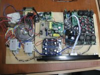
First off. How large and stiff a transformer do you need for feeding 4 op amps. 30VA should be more than enough even when you are using a Super Regulator . Right? Well I found for mylsef this weekend that it is not so. It is distinctly different when I changed to a 80VA Plitron toroid that is conservatively rated. What is the difference? The foundation of the music is fuller but leaner and more distinct. Bass lines are much clearer. Previously when I had used larger transformers, in my preamp I used a 160VA toroid but I never compared the sound of transformers like I did here. So now my IV section is fed by 80VA toroid that goes through a Jung Didden Super Regulator.
Next thing I did was I studied the AVCC Jung Sulzer AVCC power supply using an AD817 right now. Then it occurred to me that I was using a 4.7uF tantalum that was part of the RC filter for the reference voltage as was speced many many years ago. So I changed it out to a stack of metallized polypropylene caps of equivalent value and listened. I was not expecting this. The change was for the good. Now the detail of all arrangements in the music is clearly heard. The more interesting part is that the imaging solidified in depth now. While the sound is more distinct it is not accompanied with higher tonality and harshness that many many mistake for detail. Increased detail with harshness will mask the inner sounds of what is being played, in this case, the inner sounds are released and the masking or veiling is removed. So for those using an op amp somewhere for the AVCC power supply, you might want to try some films and see if you can gain something there.
I also took the time for feed the DVCC and clock power supplies from a separate transformer. It now looks like the separate enclosure I purchased for the transformers is getting too small now.
Well its time for the holidays so modding days are definitely for the New Year now.
Attachments
Last edited:
Is the AD4898 specified for use on single rail voltages? I have checked and see neither any mention nor specification when and if used with single rails.Yes it's somewhat of a minefield.
What sounds better or more transparent, the SPDIF or USB? Obviously
given same source material.
USB *should sound better if it's done right. It really is worth running the
DAC synchronously, ie; USB / I2S, internal ASRC disabled, to see where you are at.
That would answer a lot of questions. Most SPDIF have poor jitter rejection
at low frequencies so it then loads the job on to the 4137 - which also may
be poor, we don't know, then it's on to the DAC and it's DPLL settings.
Also, have you tried ADA4898 for I-V yet or are you still holding out because
data sheet looks (in some ways) bad? These are very god opamps. If you do
a bit of searching most people find them superior to the ones you have used.
T
- Home
- Source & Line
- Digital Line Level
- ES9038Q2M Board