@linuxfan,
Don't know that I would refer to the cymbals as bright per se. Rather, perhaps as forward, and with little analog obfuscation as can happen from too much of a certain type of vintage treatment.
Don't know that I would refer to the cymbals as bright per se. Rather, perhaps as forward, and with little analog obfuscation as can happen from too much of a certain type of vintage treatment.
Will you publish the complete bill of material?
You bought every composant at Mouser?
I can provide the BOM from Mouser, which is most of it. There are a few items I had on hand already, mostly some opamps and a few miscellaneous supplies. Will get to it soon.
I can provide the BOM from Mouser, which is most of it. There are a few items I had on hand already, mostly some opamps and a few miscellaneous supplies. Will get to it soon.
Thank you
terry22,
You are very welcome, of course!
May I ask if now that you have seen a few part pics and have some ideas about how it might be constructed, if you feel you could draw up a layout drawing for the whole output stage? Good to give it a try if you can, because like I said before if you don't have me to do it then best if you have some practice planning a layout on paper. It is what I often do myself because it is something to best think about before you start soldering.
Hi Markw4, others,
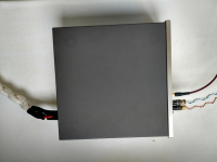
At the beginning of this thread I bought the basic DAC-board and boxed it into an old tuner case. Attached are some pictures. As a simple +/- 15V power supply serves a John Linsley Hood ripple killer followed by a classic LM317 / 337 modified as per JBeau in a hardly noticed diyaudio thread. The wiring is all solid core wire. As you may notice on the photo I am using my diy cables (also solid core) for mains, interlink and SP-DIF. I will not expand on that in order to prevent this interesting thread from the usual flames, but it merely illustrates my long quest in audio. As for the question whether diy’ers are interested in more specific ‘guidance’ in modifying, I enjoy the concreteness of the past weeks. A blog type write-up is excellent in a fuzzy front end, and now it enters a practical level where diy’ers like me can chime in. The build challenge is in the detail. In the past 35 years, as a non-EE I have learned how to read and understand schematics, and convert them into a working unit. A pcb-layout, or preferably a pcb, really contributes to a successful build. So please continue this adventure.
As for the sound of this – still unmodified – es9038q2m, I recently had the opportunity to compare it with several commercially available dacs of undisputable make, but containing a different kind of dac. The ES9038q2m sounded very much ok within the limits discussed in this very thread, be it that the mid/low area is somewhat shy. Alas, that is exactly where music comes to life. Some say it is inherent to this type of dac, but I am open to explore the diy-options for improvements. So yes, I am curious and prepared to heat the good old Weller. As you may see from the picture, lots of room available for adding some additional circuits.
Attachments

Last edited:
So, question would be, is this type of thing doable for beginners who don't want to do SMD?
Yesss, that's the way I like it. So I have many components and materials for this technique.
Hi av-trouvaille,
Welcome to the group here in the thread. Hope you find some things that work for you to improve your dac. We are always happy to try to answer questions and help out as we are able.
Welcome to the group here in the thread. Hope you find some things that work for you to improve your dac. We are always happy to try to answer questions and help out as we are able.
Hi bih,
Good to see you are comfortable with that type of approach. Will you be making up a layout drawing to share with us here? I encourage everyone to give it a try for reasons I have talked about in some previous posts.
Good to see you are comfortable with that type of approach. Will you be making up a layout drawing to share with us here? I encourage everyone to give it a try for reasons I have talked about in some previous posts.
Hi Markw4!
Which LT6655 should I prefer: Initial Accuracy:0.025 % Temperature Coefficient:2 PPM/C or Initial Accuracy:0.05 % Temperature Coefficient:5 PPM/C? Thank you! D'
Which LT6655 should I prefer: Initial Accuracy:0.025 % Temperature Coefficient:2 PPM/C or Initial Accuracy:0.05 % Temperature Coefficient:5 PPM/C? Thank you! D'
...Will you be making up a layout drawing to share with us here? ...
Yes I will, but until now, I'm not sure about the diagram for the I/V section. Is it one of those?
And witch opamps are recommended?
I can start with the design on a green hole board until my es9038 is from china in switzerland.
Attachments
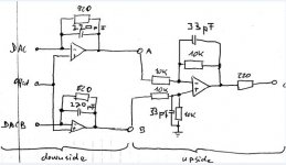
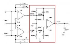
It is the printed drawing on the right with red box. There should be 3 sockets for standard pinout dual opamps. One dual I/V opamp per channel, and one dual opamp for differential summing of both channels. Add decoupling and local filter caps as appropriate/needed. Different opamps can be tried, but LME49720 should be good. Plan to eventually mount this board at the end of the dac board approximately as shown in the mockup back at: http://www.diyaudio.com/forums/digital-line-level/314935-es9038q2m-board-246.html#post5532648
It could be flush or offset in height, whatever, so long as it is stable. Most important thing there is to allow space at the edge of the output stage board for it's ground plane to extend to the ground plane of the dac board.
Approximate component sizes are shown in the picture here: http://www.diyaudio.com/forums/digital-line-level/314935-es9038q2m-board-258.html#post5539692
Thank you for being the first to say you will give it a go. 🙂
Last edited:
Attached is a list of parts I ordered from Mouser.
The first couple of items are bypass caps. The next two caps 1500pf and 330pf are options for the I/V stage caps. Most of the Sabre designs seem to use smaller caps there, so although the schematic says 1700pf, I think I will try 330pf for that.
The remaining items are the other resistors and capacitors. All the caps are small physical size aside from the tantalums. Most of the resistors are fairly small, with the largest physical size being the nominally 220 ohm I/V resistors (or 221 ohm). (The black 221 ohm resistors are shown in the example picture of components back a few posts.)
Copper foil to make a ground plane is available at multiple places such as ebay and Amazon. DIP sockets likewise.
Recommend to have thin gauge solder and wire wrap wire or similar small size for signals. Power wiring should probably be thicker gauge to help keep resistance low back to the power supply or nearby bigger filter caps.
In case anyone would be interested to know: I have been using 1,000uf and some film caps on my 1st dac board for the +-15v rails. That isn't too much to affect stability of my voltage regulators. There are many options for power supplies, including LDO RF regulators for parts of the circuitry with good PSRR at low frequencies. I opted to go for lower gain successive linear regulators for the +-15v, and an LT3042 board for shared 5v power to all boards including AK4137. I figure that would probably be okay because most everything has additional regulators to drop the 5v to 3.3v locally.
Attachments
Last edited:
Hi Markw4!
Which LT6655 should I prefer
Hi Deenoo,
Given how expensive LT6655 parts are, I would say the cheapest 3.3v one will be fine. What is also expensive are proper output filter caps for it. I ordered a couple of those that are recommended in the applications section of the LT6655 data sheet and they were about $5 each, not to mention they are physically large. For the original dac board I used a X7R output filter cap which I know will cause piezoelectric noise, but it was all I had in stock at the time. When I do a through hole component AVCC supply I will use one of the big, expensive through hole caps that I have.
Also, unless you are very experienced at soldering very small parts I would definitely recommend soldering LTC6655 to an adapter board as I tried to show in a previous post. I soldered some of the pins of the first one directly to the dac board ground plane and I think that was about has hard as anything I have done.
Last edited:
...Everyone who wants to build one of these through-hole components boards should give this layout task a try...
Well, it has been a good 3 days and only bih has expressed any willingness to attempt a layout sketch. I hope somebody has at least tried or is planning to, even if without being willing to say so publicly.
Given the lack of responses other than bih's, I guess I will stop waiting around and try to pick up the momentum with some activity here. Have some other things to do first, but I will try to get to it sometime after that.
Last edited:
hello Mark
i will do the board as well , but in 2-3 weeks from now due to work.
Also wanted to ask you if there is a point in doing any upgrades to the src4137 board.
i will do the board as well , but in 2-3 weeks from now due to work.
Also wanted to ask you if there is a point in doing any upgrades to the src4137 board.
Well, it has been a good 3 days and only bih has expressed any willingness to attempt a layout sketch
We are not all retired...😉
What precious little time is available we would like to be doing 🙂... not pondering how the pattern in the wallpaper will line up....
( My father, bless him, would spend every evening meal outlining how he proposed to hang the wallpaper in the main room.....6 months of blow by blow "I think this is what would work best, we'll start like this..."....to this day I and my siblings can't abide over-planning... make a start then figure it out and if it's not perfect then at least it can be fun !!)
hello Mark
i will do the board as well , but in 2-3 weeks from now due to work.
Also wanted to ask you if there is a point in doing any upgrades to the src4137 board.
No, to needing to mod the AK4137 boards that I know of. They are purely digital. Maybe a slight chance better clocks could help a little, but jitter is already pretty low judging by possible DPLL bandwidth settings in the dac registers.
Also, it might be possible to better help minimize jitter by soldering wires between AK4137 board and dac board instead of using pin connectors, but I am not ready to try that yet myself. Maybe ufl connectors would be good if someone wants to try that. However, to really know if you are doing any good you need to have an Arduino so you can try different DSD DPLL settings.
Regarding the prospective 2-3 week time frame you mentioned to start a layout drawing, I don't think others will want to wait that long for layout drawings to get all settled before being able to start on a board. Therefore, I will go ahead and try to get something going here. If you want to do one for your own practice when you can, I would still encourage it. But, I may post some spoilers in that regard pretty soon. Up to you if you want to look at them or defer.
If you want, we could try another layout project later when you have time. Have to think more about it between now and when you are ready if you think you might want to do something like that.
Last edited:
terry22,
You are very welcome, of course!
May I ask if now that you have seen a few part pics and have some ideas about how it might be constructed, if you feel you could draw up a layout drawing for the whole output stage?
Hi Mark,
I think I am too inexperienced to draw a output stage layout.
What I expect is to learn from this tutorial in order to be able to do it in the future.L
Thank you for the BOM
We are not all retired...😉
What precious little time is available we would like to be doing 🙂... not pondering how the pattern in the wallpaper will line up....
Understood. Don't know much about wall paper. A quick layout drawing before soldering should not be a long time consuming task. But, it should be part of the DIY builder's project. Might take me an hour, I don't know. Maybe more maybe less. Not half a day.
Last edited:
- Home
- Source & Line
- Digital Line Level
- ES9038Q2M Board