You might try looking at some of these:
Intersample Overs in CD Recordings - Benchmark Media Systems, Inc.
A Look Inside the New ES9028PRO Converter Chip and the New DAC3 - Benchmark Media Systems, Inc.
Inside the DAC2 - Part 3 - Power Supplies - Benchmark Media Systems, Inc.
Inside the DAC2 - Part 2 - Digital Processing - Benchmark Media Systems, Inc.
Inside the DAC2 - Part 1 - Analog Processing - Benchmark Media Systems, Inc.
https://benchmarkmedia.com/blogs/ap...chmark-dac2-vs-dac1-side-by-side-measurements
https://cdn.shopify.com/s/files/1/0321/7609/files/DAC3_Series_Manual_Rev_B.pdf?9982830537634228604
Benchmark herald their measurements as the gold standard but the reality is that there are plenty of DAC's that achieve as good or better - if measurements are your design intent.
For example here is measurement of PCM1794 shoved in a breadboard with
simple OPA2134 I-V. This is using EMU1212M *without*
fundamental (1kHz) notch filter so we are also seeing ADC distortion.
I guess the irony is how careful you have to be with ESS DAC to get great measured performance and how easily these were had from 1794.
Most likely true current (Hi Z) OP (of 1794) has something to do with this.
http://www.diyaudio.com/forums/digital-source/221743-testing-pcm1794.html#post3206300
Looks pretty good to me! 🙂
Terry
Terry, Maybe a good example of why not to rely on THD@1kHz as representative of much? Must be some reason not everybody is making dacs with PCM1794, and you probably know what it is. Much worse performance at 96kHz than at 48kHz is likely part of it.
Anyway, I think we all know, I hope we do, that with dacs and most other hi-fi equipment one should both measure and listen. Failure to do either one can result in significant problems.
Anyway, I think we all know, I hope we do, that with dacs and most other hi-fi equipment one should both measure and listen. Failure to do either one can result in significant problems.
Last edited:
Terry, Maybe a good example of why not to rely on THD@1kHz as representative of much? Must be some reason not everybody is making dacs with PCM1794, and you probably know what it is. Much worse performance at 96kHz than at 48kHz is likely part of it.
Anyway, I think we all know, I hope we do, that with dacs and most other hi-fi equipment one should both measure and listen. Failure to do either one can result in significant problems.
WRT measure and listen agreed.
WRT 1794, actually DAC appears to be optimized for around 384k (= 8 x 48kHz). So at 96k it's working double that.
I think the best implementations are with external filters using as little of the
internal architecture as possible (this goes for many DAC's). I've seen implementations of 1794 with external filters that do better than -120dB
distortion products and that is with addition of measurement ADC. So it's hard to know what they are actually capable of.
Their big advantage is the very benign true current OP.
Terry
To keep the ball rolling, I wanted to mention that I've been collecting the various bits and pieces to do the upgrades you have mentioned on the Chinese board. So far I've got the following:
LT3045 3.3v regulator
"Budget" AK4137 SRC board
Arduino Due and DimDim's Universal Signal Isolator board for use with his HiFiDuino code to hack the 9038Q2M's registers. (TFT display still on the way)
$7 logic analyzer you mentioned in the thread (another rabbit hole to go down for sure)
CCHD-575-50-100 clock crystal
I also have a 15V "ClassA" power supply that should work for the analog section.
I've also got an E-Mu 0204 ADC/DAC that has pretty decent specs that I'm thinking of trying to do some measurements of the board with RMAA, to make some mea surements along the way. It's probably worse from a noise perspective than a well designed 9038Q2M DAC, but it might be a good starting point, particularly if the Chinese board is particularly bad to start with.
You can get pretty good results with Emu 0204. It uses AK5385 ADC.
The EMU 1212M is better using AK5394 ADC but Emu drivers are known to be a PITA and fraught with problems. My 1212M goes out to lunch regularly
requiring a system re start. Very frustrating.
T
To keep the ball rolling, I wanted to mention that I've been collecting the various bits and pieces to do the upgrades you have mentioned on the Chinese board. So far I've got the following:
LT3045 3.3v regulator
"Budget" AK4137 SRC board
Arduino Due and DimDim's Universal Signal Isolator board for use with his HiFiDuino code to hack the 9038Q2M's registers. (TFT display still on the way)
$7 logic analyzer you mentioned in the thread (another rabbit hole to go down for sure)
CCHD-575-50-100 clock crystal
I also have a 15V "ClassA" power supply that should work for the analog section.
I've also got an E-Mu 0204 ADC/DAC that has pretty decent specs that I'm thinking of trying to do some measurements of the board with RMAA, to make some mea surements along the way. It's probably worse from a noise perspective than a well designed 9038Q2M DAC, but it might be a good starting point, particularly if the Chinese board is particularly bad to start with.
Further to my previous post here are some ES9018 measurements done with
EMU 0404 and *no* input notch filter. 0404 uses PCM1804 ADC with actually
worse specs than EMU 0402 AKM ADC, so as you can see with a bit of tweaking very good results can be had.
http://www.diyaudio.com/forums/vendor-s-bazaar/240287-es9018-dac-amp-controller-30.html#post4395582
Good luck!
T
Last edited:
Further to my previous post here are some ES9018 measurements done with
EMU 0404 and *no* input notch filter. 0404 uses PCM1804 ADC with actually
worse specs than EMU 0402 AKM ADC, so as you can see with a bit of tweaking very good results can be had.
http://www.diyaudio.com/forums/vendor-s-bazaar/240287-es9018-dac-amp-controller-30.html#post4395582
Good luck!
T
Awesome, thanks for the info. Yes, I know what you mean about the E-MU driver. I've loaded it up on a Windows 10 desktop, and it crashes on me if I try to run the sampling rate too high.
Two I2S sources in a thigh chassis
What I got
HUD-mx2
What I want to build
ES9038 with display control and with two I2S inputs (USB and Bluetooth 5.0).
ES9028 DAC DSD Decoder Board Supports IIS DSD 384KHz Coaxial Fiber+TFT LCD | eBay
USB interface
XMOS + CPLD USB Digital Interface Module HiFi Audio Board DSD256 I2S SPDIF Out | eBay
The switcher between the two sources
Two-way audio I2S / IIS switching module! pick one of two! | eBay
This Item with an antenna connector was only found at ali:
BTM875 B CSR8675 Bluetooth 5,0 Modul I2S/SPDIF Digital Audio Ausgang Differential Analog Test Backplane in BTM875-B CSR8675 Bluetooth 5,0 Modul I2S/SPDIF Digital Audio Ausgang Differential Analog Test Backplane aus Ersatzteile auf AliExpress.com | Alibaba Group
The Power Station
https://www.ebay.ch/itm/115V-230V-3...sformer-15V-15V-9V-9V-For-Preamp/263672891166
The Filter Station
https://www.ebay.ch/itm/HIFI-DAC-Po...y-Board-12V-5V-replace-LT1963AEQ/132118004269
And all together in a nice chassis like this one:
https://www.ebay.ch/itm/length-180m...S9038Q2M-DAC-with-display-window/132715077819
That would be tight but should be possible
Planed Mods are:
AVCC with two of them
https://www.ebay.ch/itm/LT3042-Low-...785977?hash=item1caa82d7f9:g:ItEAAOSwKApa8AGj
Digital 3.3v and DVDD mods with the same module like the AVCC
Now my questions to the community:
- Do you think with my new project I can beat my HUD-mx2 (PCM1796 DAC)?
- Is it possible to switch two I2S sources with this module and get the full speed?
- Is it necessary to have separate transformers for the power mods?
- Can I use the 2x9V for all the mods (1x9V for AVCC an 1x9V for 3.3V and DVDD)?
- Are this mods enough to beat my HUD?
I know, it’s hard to say this sounds better than that but I have no idea how the 9038 could sound with the simple mods in my case.
Thanx for your help
Hans-Peter
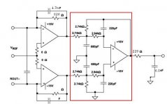
Continuing along with thinking about a through-hole output stage with adequate filtering, I am kind of thinking along lines of the schematic attached below.
It is an adaptation of a design shown in an Analog Devices op amp book, and may have been something originally designed by Scott Wurcer. The first part of the circuit on the left is just the usual I/V converters with the added possibility of trying a 'Rasmussen' style input capacitor, if anyone wants to experiment with one. (Maybe something around 100pf or 200pf could be tried if desired. Caps could also be connected from each input to ground rather than differentially, if one approach seems to sound better than the other. If experimenting with any circuit values, including trying any input caps, I would suggest measuring the effects on frequency response and phase response in the audio band, as well as distortion, in order to make sure various possible effects are well understood.)
The right side of the schematic shows the differential summing stage with filtering, which has been outlined in red. The filtering is a type that could be described as a balanced Low-Pass Multiple-Feedback (MFB) Architecture. If interested in understanding more about that type of filter, perhaps worth looking at the TI SLOA049B Application Report starting on page 7.
The reason for wanting to try this version of an output stage is that it is a pretty gradual transitioning nominally 75kHz corner frequency multi-pole filter with effective attenuation over a very wide range of frequencies, and which has a low likelihood of producing any audibly objectionable artifacts.
EDIT: Thought I might also mention the I/V stage RC corner frequency as shown should be around 120kHz. I notice that in some of ESS recommended schematics they are using a considerably higher corner frequency there, and maybe there is some reason for it such as to keep the offset virtual ground effect at the input node working effectively at some of the higher frequencies coming out of the dac. If so, it might make more sense to try reducing the cap labeled 1.7nF to something quite a bit smaller, maybe 1/3 to 1/5 of the value shown on this version of the schematic.
Attachments
Last edited:
Hi bih, You have a lot of questions!
Don't know if you can beat your current dac or not since I never heard the one you have.
Also, maybe it could be possible to find cheaper price on the Chinese ES9038Q2M dac board you have in mind, not sure.
In addition, those cases like the one you linked to are pretty small. Probably too small for all the stuff you want to put in there. You could maybe buy a small case and use the nice looking front panel attached to a bigger case, don't know.
However, mostly my opinion would be I think you are trying to go about doing this in maybe not quite the best way. For one big thing, you didn't say what you were thinking about doing for a proper output stage. That is a big consideration. Then, you didn't say anything about a clock upgrade, or upsampling to DSD with AK4137. Nothing about Arduino either. Also, your choice of AVCC supply is probably not ideal for best sound quality. If you want to beat the dac you have now and get really good sound quality, the best thing is probably not to make a list of stuff to buy as the first step, at least not the list you have now.
If you haven't been reading along with the thread for very long, there is a list of posts I can give you that you could consider reading. It would at least be easier than reading every post in the whole thread to get up to speed on some things that could help you make a very good dac.
Okay then, getting back to prospective output stages, I did some looking around at Mouser and it looks like decent leaded resistors are available at similar prices to SMD. Maybe in some cases leaded might cost more. Also, tighter tolerances may be available in SMD types.
For the schematic I posted a couple of posts back, all of the resistors should be .1% tolerance thin film or metal film. Using even tighter .01% resistors might do a better job for canceling common mode distortion though and could be used for all I/V and differential summing and filtering. The one output 220 ohm resistor should not matter so much in terms of the tightest tolerance.
For SMD, I guess I kind of like Vishay PLT resistors. For leaded resistors, Vishay is still a good brand perhaps to consider, but I have no real preference.
All the capacitors shown in the schematic should be C0G or NPO dielectric types. Not shown are power supply decoupling caps for each opamp which should be .1uf X7R and 10uf tantalum in parallel from each opamp power pin directly to the ground plane. There are a total of three dual opamps needed, which could be put in sockets. LME49720 are recommended, but can be sensitive to nearby DECT phone base station emissions unless the dac is put in a steel case for shielding. If such a problem is suspected, unplugging the phone base station power could confirm the problem.
The schematic only shows the parts for one channel, left or right. The two I/V opamps for one channel can be in one dual opamp, such as the 49720. The two differential summing opamps, one for left and one for right, can be in a third dual opamp. So, three opamps in total, and thus 6 sets of decoupling caps needed. In addition to decoupling, you may find some extra local energy storage capacitors on the output stage board help improve sound quality. Maybe 1,000uf or more for each +-15 rail, and perhaps some film caps for higher frequencies if desired.
If any questions about anything so far, please lets's discuss as needed.
I will probably order some leaded parts to make an output stage board roughly like I mocked up the other day. Probably will also order some parts to do AVCC similarly since I want to test it all on a new dac board. Thus, I will be posting a prospective AVCC supply soon, along with an LTC6655 reference mounted on an SMD adapter board. Sorry, an adapter board is the best I can do to reduce the burden of having one SMD part in the AVCC circuit. LTC6655 chips are smaller than the IC I soldered in the video I posted the other day. If people would like picture or a video showing how to solder LTC665 to the adapter, guess that should be doable. Please let me know if something like that is wanted.
Last edited:
I'm not getting your math..
The XMOS and DAC combo is $249 itself. (with the DAC board including a soldered 9038PRO chip)
Add $60 for the 3.3 V supply,
$20 for the FIFO reclocker,
$25 for the display and encoder(may be used to select inputs..)
and you are already at ~$355.
You also need a Bipolar 12V supply, which looks to be another $60, for a total of $415.
Transformers for the power supplies are not mentioned so add another $20 each for them (guestimate) (2). Connectors and switches will cost you another $30, plus add at least $100 for a case(I'm lowballing this one).
Grand total now is $585USD.
The particular case will have to be determined by yourself using the boards and other components themselves to do a physical layout, to find what case size will be appropriate.
My mistake was to add up the DAC board without the DAC, which of course is impossible.
The power supply is dual, so you do not need another one. My final account seems to be $395 in boards, leaving just the case and transformer cost to add.
My mistake was to add up...
I can't tell from the seller website what you would need to order, but here is the way it looks to me:
You can buy ES9038PRO board and dac board, whatever that includes.
You probably do want the volume control, since the digital volume control is far superior to analog. Our Chinese dacs come with digital volume control built in.
Somehow or other, output stages usually need +-15v highly regulated supplies. The ES9038PRO chip needs general purpose 3.3v and 1.2v power supplies. You may need 5v power for some odds and ends.
And you need two super quality, super low noise 3.3v supplies for AVCC. If using LT304x LDO RF regulators for AVCC, I would strongly suggest modifying them to use an LTC6655 reference. One of the LT304x data sheets shows the application circuit for doing that. It reduces LF noise in the audio band since RF regulators tend to have a lot of 1/f noise and the AVCC inputs on the dac chips have no PSRR at all to reject it. (Opamps are probably okay with RF regulators without LF low-noise references, only AVCC is critical )
For our dacs here, we don't find a FIFO is needed, but these ESS dacs sound better with upsampling and conversion to DSD, so an AK4137 board from ebay or aliexpress for that might be $40 - $80 depending on features.
We also tend to do low-jitter clock upgrades, don't know with the dac kit comes with. A good Crystek clock is maybe $30.
I like to add a headphone amp which is the only way most people can really tell how well the dac is performing since most people don't have amps and speakers good enough to fully reveal what a good dac is capable of. A HPA kit that can be modded with some work is maybe $32.
Transformers would be needed for all the power supplies. I use two transformers myself. One for +-15v, and the other for a 5v supply. The 3.3v supplies are regulators that run off the 5v DC supply.
It may also help dac performance to add individual regulators for some purposes such as for the clock, which helps reduce jitter. I also have my VCCA supply on a separate regulator.
Then it turns out you can improve the sound quality of these ESS dacs if you can get in and access some of the control registers. Things like DPLL bandwidth and harmonic distortion compensation can improve sound quality. Also, somehow you probably want to be able to select input sources, select reconstruction filters, etc., the $29 digital volume control may or may not let you do some of that. Not likely it would let you do all of it. We use an Arduino microcontroller to access the ES9038 registers in our modded dacs.
Don't know if you only want SPDF in or if you want USB too. An Amanero or XMOS board for USB audio is maybe $40 - $100. Looks like you can buy the dac kit with that included, although I didn't see any USB connector and other stuff for that in any of the pictures.
Then there would be the question of a case, if desired.
Last edited:
Don't you think film polypropylene caps might sound better than COGs or NPOs?
Polystyrene might even be better, but are hard to find.
What regulated supply are you planning to use for that output? Perhaps 1000uF local bypass might not recommended depending on the regulator.
Polystyrene might even be better, but are hard to find.
What regulated supply are you planning to use for that output? Perhaps 1000uF local bypass might not recommended depending on the regulator.
software modded Tone Board
Hi all,
I was very busy the last weeks, I was working on customizing the xmos firmware of the tone board. It's a success 🙂
What I've achieved:
Dump the es9038q2m register through a arduino board. ( I noticed very low thd compensation value)
Save and restore the stock firmware ( with a jtag xtag3 adapter (18 $))
Develop my own xmos firmware with hardware volume management.
Measurement
I've done some comparison between my es9038q2m modified chinese board (avcc with aop, thd compensation and a good linear supply) and the tone board.
SNR: Tone Board is better ( Samsung galaxy usb adapter + raspberry pi + volumio), I've tested several supplies ( linear , SMPS) , the galaxy usb adapter doesn't generate to much noise, the I/V stage seems to be noise immune .
THD@1Khz : my customized es9038q2m board is better (feed by an xmos card coax output) by a small margin, thd compensation helps a lot.
So voltage mode is not so bad if the thd compensation is enabled.
Don't you think film polypropylene caps might sound better than COGs or NPOs?
Polystyrene might even be better, but are hard to find.
What regulated supply are you planning to use for that output? Perhaps 1000uF local bypass might not recommended depending on the regulator.
Thank you for your comments. We appreciate your interest in the project and willingness to help.
However, no to the other caps in this case. C0G and NPO are as good as caps get. Only problem with them is they are only available in small values. For larger values then we would consider other dielectrics as you recommend. Also, remember we are trying to filter out some very high frequency content possibly as much as 100MHz. We want caps that sound good and work well for pretty high frequency RF too.
Regarding 1,000uf caps and regulator stability, it should not be a problem if there is a little distance between the caps and regulator. If too close to a very high gain feedback regulator then we might not want to use that much capacitance, but I rarely see a problem with it. Also, my preference is usually more for successive stages of lower gain regulation more than one stage of super high gain regulation. Not always though.
Last edited:
So voltage mode is not so bad if the thd compensation is enabled.
Hi occip,
Thank you for the update, lots of work there. Curiously, what is possible to do with custom XMOS firmware, is it volume only? (Assume you are aware that volume control in the ESS dac chips probably preserves more bit resolution than other digital volume controls, because it can be implemented in the upsampled modulator. http://www.esstech.com/files/3014/4095/4308/digital-vs-analog-volume-control.pdf)
Also, may I ask if you can hear any difference in sound quality between the two dacs you have been comparing?
Possibly tried AK4137 yet?
Last edited:
Continuing along with thinking about a through-hole output stage with adequate filtering, I am kind of thinking along lines of the schematic attached below.
It is an adaptation of a design shown in an Analog Devices op amp book, and may have been something originally designed by Scott Wurcer. The first part of the circuit on the left is just the usual I/V converters with the added possibility of trying a 'Rasmussen' style input capacitor, if anyone wants to experiment with one. (Maybe something around 100pf or 200pf could be tried if desired. Caps could also be connected from each input to ground rather than differentially, if one approach seems to sound better than the other. If experimenting with any circuit values, including trying any input caps, I would suggest measuring the effects on frequency response and phase response in the audio band, as well as distortion, in order to make sure various possible effects are well understood.)
The right side of the schematic shows the differential summing stage with filtering, which has been outlined in red. The filtering is a type that could be described as a balanced Low-Pass Multiple-Feedback (MFB) Architecture. If interested in understanding more about that type of filter, perhaps worth looking at the TI SLOA049B Application Report starting on page 7.
The reason for wanting to try this version of an output stage is that it is a pretty gradual transitioning nominally 75kHz corner frequency multi-pole filter with effective attenuation over a very wide range of frequencies, and which has a low likelihood of producing any audibly objectionable artifacts.
EDIT: Thought I might also mention the I/V stage RC corner frequency as shown should be around 120kHz. I notice that in some of ESS recommended schematics they are using a considerably higher corner frequency there, and maybe there is some reason for it such as to keep the offset virtual ground effect at the input node working effectively at some of the higher frequencies coming out of the dac. If so, it might make more sense to try reducing the cap labeled 1.7nF to something quite a bit smaller, maybe 1/3 to 1/5 of the value shown on this version of the schematic.
How about a transformer output stage? The transformer can be part of the filter design due to its bandwidth characteristics and also provides isolation. The output can be balanced or single ended. Jensen makes good (but pricey) line level transformers which would work. And for really good performance, I would look at Sparkos discrete op amps.
Attachments
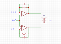
How about a transformer output stage? ... And for really good performance, I would look at Sparkos discrete op amps.
Hi wtnh, Thank you for the comments and interest.
Transformer output is a possibility. There is more than one way to do that of course, but right after IV stages should be an easy one to try. Thing is good transformers are very expensive, and they tend to add at least a little bit of distortion due to core hysteresis and sometimes saturation. Of course some people like that sound a lot, and one could say that everything has a sound, so take your pick. Opamps probably show the least measured distortion if implemented well, but we should probably use both measurements and listening to make design choices.
Anyway, I have some transformers here I could probably try as you suggest, if I ever get around to it.
Regarding discrete opamps, it may depend. I am one of the people selected as Allo Katana dac reviewers (waiting right now for them to tell me when they ship the v1.2 boards, hopefully any day now). As you may know Katana features a Sparkos discrete opamp output stage. Looks to be maybe six opamps judging by the number of offset adjustment pots. So far I have had an opportunity to compare up to v1.1 Katana dacs with my modded Chinese dac and with the Benchmark DAC-3 located here (it uses LME49860 opamps). So far, DAC-3 always easily wins sound quality comparisons, and so far Katana has not beat my modded dac, although it has tied at some points in time as both Allo and myself continue to tweak our designs. Probably for now Katana 1.2 is going to be the release version and maybe it will finally beat my modded dac. If it does, that will be great news for consumers I think, because it will be an exceptionally good dac for the price. Even if it ties that would be good thing, since both dacs are actually pretty good, and very hard to beat for the cost. I can't pin down exactly where they fit in with other upscale but <$1,000 dacs, however, they are both better than the other dacs I have personally heard in that price range.
Anyway, my conclusion so far about Sparkos opamp output stages is that it may not be the biggest bang for the buck or any guarantee of ultimate sound quality. Of course, maybe they will work better with some other dac chip or under some other as-yet-unknown-to-me circumstances.
Last edited:
Hi wtnh, Thank you for the comments and interest.
Transformer output is a possibility. There is more than one way to do that of course, but right after IV stages should be an easy one to try. Thing is good transformers are very expensive, and they tend to add at least a little bit of distortion due to core hysteresis and sometimes saturation. Of course some people like that sound a lot, and one could say that everything has a sound, so take your pick. Opamps probably show the least measured distortion if implemented well, but we should probably use both measurements and listening to make design choices.
Anyway, I have some transformers here I could probably try as you suggest, if I ever get around to it.
Regarding discrete opamps, it may depend. I am one of the people selected as Allo Katana dac reviewers (waiting right now for them to tell me when they ship the v1.2 boards, hopefully any day now). As you may know Katana features a Sparkos discrete opamp output stage. Looks to be maybe six opamps judging by the number of offset adjustment pots. So far I have had an opportunity to compare up to v1.1 Katana dacs with my modded Chinese dac and with the Benchmark DAC-3 located here (it uses LME49860 opamps). So far, DAC-3 always easily wins sound quality comparisons, and so far Katana has not beat my modded dac, although it has tied at some points in time as both Allo and myself continue to tweak our designs. Probably for now Katana 1.2 is going to be the release version and maybe it will finally beat my modded dac. If it does, that will be great news for consumers I think, because it will be an exceptionally good dac for the price.
Anyway, my conclusion so far about Sparkos opamp output stages is that it may not be the biggest bang for the buck or any guarantee of ultimate sound quality. Of course, maybe they will work better with some other dac chip or under some other unknown circumstances.
Yes, transformers will introduce distortion, but some of the Jensens, like the JT-11-BMCF are spec'd at .002% THD at +4dB. They get this by using mostly nickel in the cores. The downside of that particular transformer is that its bandwidth goes out to 15MHz!!! (so not too useful as part of the filter). The Jensens have almost perfect linear phase response (as in zero shift) in the audible spectrum. Lindahl also makes good line level units but they are even pricier.
Anyway, looking forward to your impressions of the improved Katana.
As far as Sparkos goes, I think Allo had them design the analog board and allow Sparkos to "brand" the board. For those who are not familiar, Sparkos sells drop-in discrete op amps and high-performance LDOs: Home - SparkoS Labs Inc.
Cheers
Whit
Ti has designed a PCB for Sabre DACs, though they don't say so.
Gerber files, layout etc. all done for the DIYer and someone wishing to work from.
This will drive even headphones directly or if one chooses to drive even long and exotic cables.
http://www.ti.com/lit/ug/tidu672c/tidu672c.pdf
TIPD177 A High-Fidelity Headphone Amplifier for Current Output Audio DACs Reference Design | TI.com
Don't know if eval boards are available for the headphone circuit. If so, it could be an easy way to do it.
If not an enterprising soul can then use this and combine it with possibly the DAC layout recommended by ESS and come up with a nice DAC. Thing is the LAYOUT by TI has been done for you. THAT part and they know that layout is a hit and miss thing, they's done the hard work of layout. The design and traces on the PCB is a big issue if you want the optimum.
An essential read for anyone pursuing the design of the IV section. Best design lessons I have seen in print.
Last edited:
- Home
- Source & Line
- Digital Line Level
- ES9038Q2M Board