Added myself to the list for:
1*DAC V3 PCB + 1*ES9023 DAC Chip + 1*PSU PCB + 1*SE Parts Kit + 1*PSU Parts Kit
Cheers!
1*DAC V3 PCB + 1*ES9023 DAC Chip + 1*PSU PCB + 1*SE Parts Kit + 1*PSU Parts Kit
Cheers!
Phil,
I would like to have an indication of the physical dimensions of the pcb-s (ess board and power).
kind regards,
Paul
I would like to have an indication of the physical dimensions of the pcb-s (ess board and power).
kind regards,
Paul
Hi All
asgaard thanks for pointing that, "sizing" informations added in first Post 😉
Waiting for Beta testers reports and venerable "Moderator Emeritus" opinion
I've got mine, but can't tell you more right now.
One tip I can reveal, PCB is thicker, traces are optimized, more space for your favorite caps... d'ho
Regards
Phil
Last edited:
Added myself for the SE kit. Presumably you have to fill in 5 of the 6 columns (all except the BAL column). Well, I just did it the way everyone else had done it! ;-)
Edit: Added a spare ES9023, just in case..
Edit: Added a spare ES9023, just in case..
Last edited:
don't know if this is still active, but I put my self for one SE...(miss this last time...hope it's not too late for this group buy)
don't know if this is still active, but I put my self for one SE...(miss this last time...hope it's not too late for this group buy)
No worries, we are all waiting patiently!!
Beta V3 SE
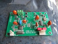
Hi all, finally got my beta boards today and I just nearly finished my first V3 beta on an official PCB. Some caps are still missing and some things will change in the final version. V3 SE is the first board that can be ordered so SPDIF only. It can only do one thing but it can do that very well. Consider this a teaser. It won't be long before the production version will appear. Please consider that the U.FL connector footprints may disappear as i feel they don't add a thing to the SPDIF version of the DAC.
The resistor array really is a tough one to solder to the board and it reminded me again why I didn't like SMD in the past 🙂 The orange caps are solid electrolyte MnO2 caps from BC Components/Vishay which perform quite good in my test DAC.
Attachments
Last edited:
Great news!!
If it sounds as good as it looks....
Please if there is any way to keep the U.FL connectors. I will not be using the SPDIF so a good, easy connection for IS2 would be beneficial to me. However, don't let that get in the way!
If it sounds as good as it looks....
Please if there is any way to keep the U.FL connectors. I will not be using the SPDIF so a good, easy connection for IS2 would be beneficial to me. However, don't let that get in the way!
Yes! Please keep U.FL connectors! ...or are you considering a different version with U.FL connections for i2s?
Last edited:
Great news but not so great news regarding the I2S connectors. Please keep them. I wanted to use a USB-to-I2S board with your DAC... I thought the connectors would be kept on the board.
Hi all, finally got my beta boards today and I just nearly finished my first V3 beta on an official PCB. Some caps are still missing and some things will change in the final version. V3 SE is the first board that can be ordered so SPDIF only. It can only do one thing but it can do that very well. Consider this a teaser. It won't be long before the production version will appear. Please consider that the U.FL connector footprints may disappear as i feel they don't add a thing to the SPDIF version of the DAC.
The resistor array really is a tough one to solder to the board and it reminded me again why I didn't like SMD in the past 🙂 The orange caps are solid electrolyte MnO2 caps from BC Components/Vishay which perform quite good in my test DAC.
JP,
Looking good!
 for u.fl.
To help those of you who are interested in the i2s input on u.fl here are some pointers to think about:
The u.fl could use a better ground connection than the current layout provides. Long traces to vias for the 3 u.fl connectors isn't great for signals that may need bandwidth upward of 300MHz, despite being digital signals with a duty cycle of maybe only a few MHz.
I know some have talked about connecting potoatosemi flip flops on an isol/reclock board to this DAC. The flip flop that will drive the input i2s signal has a rise time of <1ns. Signals this fast take some consideration in the layout. If it isn't the main focus of the design, accommodating these considerations may compromise on other functions that are deemed more important by the designers.
It really is up to the builder to understand what you're building, especially if you're using something like the potatosemi FF, they're fast and can cause problems unless they're in the designers mind from the outset.
For SPDIF users the i2s inputs are a distraction and unnecessary.
None of this is a criticism of the design's ability to do what is intended. A dedicated SPDIF board will certainly still fit a need that many people are wanting.
@J-P, I know what you mean about those resistor packs, they are a tricky beast to check that you haven't got shorts between pads that is unseen even under a magnifying glass. I always check those carefully with a multimeter to be sure. Solder wick and drag soldering is the only way I can get them done really, certainly not going to try to do one pin at a time.
Cheers,
Chris
@hochopeper - thanks for putting this into perspective. Maybe the Subbu v3 isn't for me after all. I'm one of the people wanting to try the potato semi flip flops for re-clocking and while I could do the slower re-clocking, it looks like both might not be a reality even if u.fl connections are maintained ...unless there is a different version to be had -- I'm all ears.
Just wait some more. There will be a second version.... The SPDIF version will definitely come without the U.FL connectors as the DAC will be better without them. The SPDIF version will be as pure as I can make it without any bells and whistles. I am not regretting that. The U.FL connector is a lousy connector mechanically (but it is good electrically).
We know some of you have plans with our DAC. You won't be disappointed. It might be that you get a surprise for the long waiting. I can not tell anymore as I signed an NDA with Subbu 😉
How right you are Chris ! BTW the footprint of the resistor array has been changed by Subbu as it was not entirely the right one. I managed to solder 2 boards without problem though. I used 2 magnifying glasses. These arrays' contacts are too small for my eyes.
We know some of you have plans with our DAC. You won't be disappointed. It might be that you get a surprise for the long waiting. I can not tell anymore as I signed an NDA with Subbu 😉
For SPDIF users the i2s inputs are a distraction and unnecessary.
How right you are Chris ! BTW the footprint of the resistor array has been changed by Subbu as it was not entirely the right one. I managed to solder 2 boards without problem though. I used 2 magnifying glasses. These arrays' contacts are too small for my eyes.
Last edited:
- Status
- Not open for further replies.
- Home
- Group Buys
- ES9023 / WM8804 S/PDIF "Subbu DAC V3" GB Interest