I had a chance today to tear apart a Denon AVR-2105 receiver I grabbed off eBay for about $40 since it wasn't working. Unit powers up, displays some info on the screen then shuts down into protection mode.
After some deep digging, that is taking out all 9 or so PCBs including the main one, I found the front left output PNP transistor has a shorted collector to emitter.
It's a Sanken Electronics 2SB1560 darlington which doesn't seem to exist for consumer purchase. On Digi-Key the closest thing I could find is a TIP147TU. Think this would work as a substitute? I noticed the Sanken datasheet lists a pretty high hfe range compared to the TIP. Of course I'd also be replacing its NPN counterpart as well. Thanks,

Attachments
hi
you got a bargain if you can get that amp repaired, i would not subtitute the transistor with the TIP device this will cause all sorts of problems.
the 2sb1560 are availible here although there may be a minimum order charge
Power Darlington
these guys are exelent
good luck
you got a bargain if you can get that amp repaired, i would not subtitute the transistor with the TIP device this will cause all sorts of problems.
the 2sb1560 are availible here although there may be a minimum order charge
Power Darlington
these guys are exelent
good luck
Hey that's great, I didn't really want to replace it with a different device, figured it would cause all kinds of blalance problems with the other channels.
I'm also wondering why the transistor went out in the first place. Was he using too low impedance of speaker, pushing it too hard, is the component underspec'd?...Probably a combination. Also 21 output devices on a single, passive heatsink never really looks right to me. I should add a fan for kicks.
I'm also wondering why the transistor went out in the first place. Was he using too low impedance of speaker, pushing it too hard, is the component underspec'd?...Probably a combination. Also 21 output devices on a single, passive heatsink never really looks right to me. I should add a fan for kicks.
a little bit of advice... order the parts from B&D. a bit pricy, but you won't get fakes.
also you need to check out other components. check for open resistors and shorted semiconductors in the blown channel. there's a base drive clanp consisting of 2 signal diodes and 2 zener diodes. the zeners are usually 4.7V or 5.1V in a denon. the zeners and diodes may be SMT diodes on the solder side of the board.
also you need to check out other components. check for open resistors and shorted semiconductors in the blown channel. there's a base drive clanp consisting of 2 signal diodes and 2 zener diodes. the zeners are usually 4.7V or 5.1V in a denon. the zeners and diodes may be SMT diodes on the solder side of the board.
Good advice, I figured something else may have taken a hit when the transistor went. I just need to find time to do a little more digging. The plan is to get this thing working before finals hit. Don't really want to take it on a roadtrip when its all apart like this.
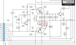
I traced it back as far as I could go and found 2 open 0.22ohm resistors in parallel, in series with the emitter of the blown transistor. Made a lot of sense to me.
you probably will find more... the resistors you found are the emitter resistors for the output transistors. the base circuit may also have some problems, as well as the bias circuit and possibly the VAS stage.. you can use the other channel to compare in-circuit readings against.
I checked every resistor and diode from the preamp to the amp and out to the mains and I found nothing else that was off. I attatched a pic of the amp schematic so you can see how it's laid out. To me it seems like those resistors would be the only casualties since they are the only other components directly in the output loop, along with that inductor of course. Maybe I'm wrong though, I don't have a lot of experience with this stuff yet.
Attachments
Last edited:
ok, hopefully that's all there is. another thought... when you talk to B&D, see if you can get the output devices with matching beta codes. the beta code is part of the date code. for instance the date code of 59Y means that the device was made in year 05 (the 5), September (the 9), and has a bets between 15000 and 30000 (the Y).
beta codes are O, P and Y, O=5000-15000, P=10000-20000, and Y=15000-30000 IIRC.
beta codes are O, P and Y, O=5000-15000, P=10000-20000, and Y=15000-30000 IIRC.
hi guys. can anyone help me to find an equivalent transistor for my transmitter? The blown transistor is PT8860 but i can't find it no where... any help will be appreciated.
- Status
- Not open for further replies.
- Home
- Design & Build
- Parts
- Equivalent transistor
