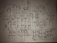
Got a monstrous amp and it is suppose to be super high tech where at low volumes it uses the triode strapped EL34 and at higher power switches to UL KT88. Problem is when I went to analyze the "secret module" that is between the plates of the power tubes I believe it is just a wire in epoxy. I have not melted the epoxy yet to see what is inside but there are only 2 connections going into the module which connect to the plates just like tge schematic, it has perfect continuity just like a short piece of wire. No other connections at all.
Anyone familiar with these amps? Is this secret module just a hoax?
Anyone familiar with these amps? Is this secret module just a hoax?
Attachments
Possibly, I will check its impedance at high frequencies.
The designer claims a lot more from this secret circuit than an inductor.
The designer claims a lot more from this secret circuit than an inductor.
I will upload the circuit description, when I find it but they are claiming that magic box does a lot, some sort of switching between low power (EL34) and high power (kt88).
On page 40 of this 1953 issue of Radio & Television News there's a description of a similar amplifier (with a pair of 807's running in triode mode + a pair of 807's running in pentode mode): https://worldradiohistory.com/Archive-Radio-News/50s/Radio-News-1953-09.pdf
No 'Secret Module' in that amplifier though.
No 'Secret Module' in that amplifier though.
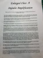
Exactly!! Thank you, I forgot what it was called, "extended class A" and as I thought there is zero need of a secret module to do anything!! That is what we call marketing folks. The amplifier I have had nothing but issues, notice the huge capacitance with tube rectifiers. Later models have SS rectifiers but kept blowing secondary windings in the PT.
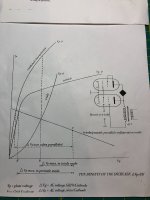
Interesting articles. So basically triodes in class A in parallel with tetrodes in Class C.
Conspicuously absent is any discussion of how they pick the OPT primary impedance. It can't be optimal for both PP and PPP, can it?
Conspicuously absent is any discussion of how they pick the OPT primary impedance. It can't be optimal for both PP and PPP, can it?
It might sound better with the magic box pulled out.
I agree!!
I got ahold of the product documentation.
That certainly is a large dose of BS consistent with the secret magic box between the anodes. However the circuit works, just a matter of how and how well. I will put it in LTSpice when I have some time and see what it does.
Thank you!! My engineering computer is down at the moment so I havent been able to put it into LTSpice. Curious what you find.
i heard both version of this amp; the one with silver opt is exceptional, but the one with copper opt is very ordinary.
there should be a 47 to 100 ohm resistor between the rectifier ( tube or SS ) and capacitor bank. this would reduce stress on the rectifier and output coils.
if it is a SS bridge, the B+ will still be higher.
the "Magic box" won't do much on the anode side. those two tubes have different mu (gain) as well.
They must be driving the EL34 hard and letting the 6550 keep the plate dissipation reasonable. this would add possibly very pleasing distortion to the amp.
My next project is a 100w 12AX7 and 6922 amplifier. 30w sounds fantastic
Last edited:
- Home
- Amplifiers
- Tubes / Valves
- Equilibre amp