Hello Everyone -
I need a little advice here. I built the EPE Magazines 20W Class A amplifier. I did not use their PCB, but rather designed my own. I ran into a problem with not being able to set the bias. After examining several other amplifiers, I added the two capacitors (in RED) to the circuit, and now it sets bias perfectly and runs great. I also subbed the 2SA transistors with BC560 low noise devices. Could anyone tell me if adding the capacitors will deteriorate the amps reproduction quality. It sounds fantastic, but I'm no engineer and just wanted to verify/disqualify my modification. Thanks!
I need a little advice here. I built the EPE Magazines 20W Class A amplifier. I did not use their PCB, but rather designed my own. I ran into a problem with not being able to set the bias. After examining several other amplifiers, I added the two capacitors (in RED) to the circuit, and now it sets bias perfectly and runs great. I also subbed the 2SA transistors with BC560 low noise devices. Could anyone tell me if adding the capacitors will deteriorate the amps reproduction quality. It sounds fantastic, but I'm no engineer and just wanted to verify/disqualify my modification. Thanks!
Attachments
It looks like the schematic for the Silicon Chip magazine 20W class A design from May 2007, IIRC. I understand EPE republishes the designs a couple of years later. I built a few of the kits without any issues or need for modification apart from buzzing transformers - a side effect of cheap toroids that weren't designed to be silent.
http://www.photonage.com.au/images/images/prod/K/K5125.jpg
The 2SA970 transistors are actually better on noise and distortion than BC series parts but since they are now obsolete, we use KSA992.
I would not bypass the 510R feedback ratio resistor like that - it alters the frequency response significantly. Question is, are you talking about one channel or are both channels behaving that way?
An unstable bias that is fixed by altering the frequency response, should tell you that it is likely an oscillation problem and could have been caused by PCB layout, soldering, wiring or even a component issue. The layout is a little tricky with a blameless design like this - it needs to be a pro. quality job to approach the design specs.
It sounds like your amp could be unstable and oscillating at high frequency if you found adding caps 'fixed' it.
The 100nf across the large electrolytic should have no effect (and it should have no effect on your fault either). The exception to that would be if the electrolytic were faulty and had a high series impedance.
The 100nf across the 510 feedback return is definitely not good I'm afraid, in fact normally that would cause problems, not fix them.
I was afraid of that. The 100nf I put across the 510 resistor is the one that "fixed" the problem. I am showing a small amount of oscillation "fur" at the speaker outputs (about 10mv PP). the 220uf caps (on both channels) are new and both channels exhibit the same symptoms. Would increasing the value of the 220uf help? Any suggestions would be greatly appreciated... Thanks!
All I had 'on hand' were some 100pf caps, put them in (across the 10k's), an NO oscillation on the scope. The amp played for about 2 minutes then kicked the breakers.
I re-adjusted the bias (it was actually OK where it was) and ran it for 10 minutes - no problem. I don't know why it kicked out the first time, but now seems stable. Will do more testing and post. Thanks Again!
I re-adjusted the bias (it was actually OK where it was) and ran it for 10 minutes - no problem. I don't know why it kicked out the first time, but now seems stable. Will do more testing and post. Thanks Again!
OK, I found some 30pf caps and put them across the 10k's. Tried resetting the bias, but I get just past center on the pots and both channels go into oscillation. The 100pf caps would allow me to set the bias, but after a short time playing the amp will kick the breakers. Reset the breakers and it will run again for a short time. I should have noted that I have subbed 2SD555 & 2SB600 transistors for test purposes. I have a set of the right outputs (MJ21193 & MJ21194) but don't have the right heatsink yet. I may have to scrap this project (as it is) and start over. Thanks for all your help!
Make sure that 100pF NPO cap on Q8,Q9 is really there. Also, where the grounded caps connect does matter... all points "ground" are really not the same. Load ground goes to power supply common. All the grounds (shown ties together) at the input should connect together then go to the same power supply common (probably).
Pics
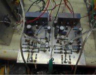
Well, I just don't get it. I put a 100pf cap in parallel with the 30pf (across 10k) and got the bias to set perfectly. No oscillation on the scope. (Yes, the 100pf NPO {Q8,Q9} is there). It fires up and sounds great - for about 1 - 2 minutes then kicks the breakers. (I'm using 2 [6Amp] breakers on the transformer's secondary.) Reset breakers, 1 - 2 minutes, kicks out again. I even swapped the 2SD/2SB's on one channel with the MJ21193/94's. No change. I will admit, the MJ's do sound better. I'm attaching pics of my (lame) setup for testing. As you can see, they are double sided boards and I have triple checked the layout for accuracy. Just can't figure out what's kicking the breakers...
Well, I just don't get it. I put a 100pf cap in parallel with the 30pf (across 10k) and got the bias to set perfectly. No oscillation on the scope. (Yes, the 100pf NPO {Q8,Q9} is there). It fires up and sounds great - for about 1 - 2 minutes then kicks the breakers. (I'm using 2 [6Amp] breakers on the transformer's secondary.) Reset breakers, 1 - 2 minutes, kicks out again. I even swapped the 2SD/2SB's on one channel with the MJ21193/94's. No change. I will admit, the MJ's do sound better. I'm attaching pics of my (lame) setup for testing. As you can see, they are double sided boards and I have triple checked the layout for accuracy. Just can't figure out what's kicking the breakers...
Attachments
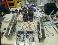
The loose wiring of your bench test setup doesn't inspire confidence for a fair test set-up. You need maximum stability so for starters, power leads (+22V, -22V and 0V) should be tightly wound together all the way from PSU to PCB connectors. Rectifer AC leads should be twisted also and kept away from signal and power. Take a look at the pic. posted in #2
You say that there is no oscillation which may be true - until it gets hot, gain increases and the amplifier probably bursts into oscillation, tripping the overload. It can be almost instantaneous but how else could the overload breakers consistently trip when rated 6A with what should be no more than a constant 1.2A bias? Can you also point where the Zobel network is located? Otherwise, the output coil and damping resistor located on the heatsink PCB are fine but I'm curious what the other parts are for.
Does the amplifier trip the breakers with no signal, no speaker load and even with grounded input - given enough time to heat up? That may clarify the situation.
The Zobel circuit is all there on the heatsink pcb. The resistor is inside the coil, the large yellow capacitor (0.15uf) completes the circuit. The other resistors are the 'emitter' resistors (although they are connected to the collectors.) It only seems to exhibit the problem when running audio through it with speakers hooked up. I will try weaving the B+/B-/Gnd wires as you suggest. I'm sure the problem is oscillation happening spuriously and instantaneously. I would really like to get this thing running stable. Thank you for the suggestions...
You got some good advice in the last few posts 🙂
I would start by running one amp on its own and making sure its 100% stable. I think a lot of your issues are coming down to how you have you have interconnected them all.
Are you running the speaker returns back to the power supply (at least for the time being) ?
You might find something of use here. Post #38 is a start but have a quick skim through it all,
http://www.diyaudio.com/forums/soli...-lin-topology-nfb-tappings-2.html#post1624677
I have built this amplifier and i haven't seen any instability problem.
I can't find this thread now but i will try later.
I can't find this thread now but i will try later.
Today I'm going to start by re-routing all the supply wires and feed wires to the finals. Will post back with the results. Thanks to everyone for their really great input on this!
Well everyone - We can CLOSE this thread. I really feel stupid, after 40 years of electronics experience, I made one of the most unforgivable mistakes I have ever made. Because I decided to mount the output transistors and Zobel circuit on an external heatsink, the NFB line also comes from the driver board to that circuit. Well guess what? I attached the NFB line AFTER the R/C/L instead of directly to the common collector isolation resistor junction. After a few hours of re-routing the wiring (as suggested) it still would kick the breakers. Then I noticed what I had done... I move the NFB line to it's proper location and Walla!!!! - Set the bias and I've been listening to it for half an hour now. Sounds Great. AND, the heatsink(s), although very warm, no longer need to be fan cooled for it to run. Thanks to everyone for their input on this and I really appreciate the response you guys all gave.
Take a look here.http://www.diyaudio.com/forums/soli...icon-chip-20w-class-amplifier-opinions-3.htmlI have built this amplifier and i haven't seen any instability problem.
I can't find this thread now but i will try later.
Don't worry!Anything that can possibly go wrong, doesWell everyone - We can CLOSE this thread. I really feel stupid, after 40 years of electronics experience, I made one of the most unforgivable mistakes I have ever made. Because I decided to mount the output transistors and Zobel circuit on an external heatsink, the NFB line also comes from the driver board to that circuit. Well guess what? I attached the NFB line AFTER the R/C/L instead of directly to the common collector isolation resistor junction. After a few hours of re-routing the wiring (as suggested) it still would kick the breakers. Then I noticed what I had done... I move the NFB line to it's proper location and Walla!!!! - Set the bias and I've been listening to it for half an hour now. Sounds Great. AND, the heatsink(s), although very warm, no longer need to be fan cooled for it to run. Thanks to everyone for their input on this and I really appreciate the response you guys all gave.
- Status
- Not open for further replies.
- Home
- Amplifiers
- Solid State
- EPE 20W Class A question