I picked up an as-is EP2500 from eBay. I did this once before and it turned out to just be a bad power switch, this one was cheaper but I thought it was worth a try. The seller knows nothing about what's wrong, etc. they're just selling it. I opened the amp and found a couple notes from a service tech in there (not a good sign for me... if a service tech couldn't fix it what are my chances!?). Anyway one of the notes was just some voltage checks they had done. The second one says:
"2nd new one. This one is also getting hot, maybe we are getting the wrong board."
Anyway I plugged it in and turned it on. Nothing blew up, fans kicked on, etc. I hooked it up but got no output. I popped it open again and found the board for the channel closest to the power supply was unhooked. Hooked it up and plugged it in and it immediately gets very very hot... Within a couple seconds you can smell the heat - way before the chassis gets hot.
I managed to track down a service manual for the QSC RMX2450. One thing it mentions is to adjust the bias. It gives specific components to test and adjust but I'm unfamiliar with schematics and was not able to find the components in the amp (also I suspect they're labeled differently in the Behringer than in the QSC...).
Is anyone familiar with these amps and where I should be looking. Also I'm considering switching out that channel on the "broken" amp with one from a working amp, anything I should know before attempting that? I've got very very little experience with this sort of thing.
Ooh, found this post from somewhere:
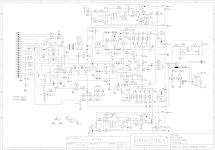
" On that schematic, there is a Bias pot VR6. That pot can be adjusted so that there is 80mV across R106. If there is no bias across R106, and either one or both zener diodes D9,D12 are bad, upon replacing the zener diode, the amp works, What other components or voltages should be checked? I thought zener diodes were kind of fragile, especially these glass kind, and excessive heat can be the cause of failure."
I've located VR6 and R106. I tested the DC voltage across R106 on my working one and got about 75mV. Tested on the broken one and got nothing... I couldn't find D9 or D12 though?
OK, another update. Found D9 and D12 on the other board. I'm not familiar with how to test a diode but I believe my multimeter has a setting for this. I tested each one and found that D9 is "bad" (produces a solid tone instead of a single beep)...
Based on this post I found on here from a 2008 thread:
"I just repaired one as well. the 15V zener diode went bad causing the amp to lock up and it took out the triac crowbar output the Fet, all the output transistors, the emitter resistors, base resistors, and just about every other component in that section. But, With the help of the QSC service manual, i was able to get it back up and running pretty easily.
The current fold back test is a bugger however. shorting the output of the amp to check for current foldback then recovery at full power into a 2 ohm load requires a BIG resistor bank!"
Sounds like I'm in over my head. This would explain why the service tech couldn't fix the amp... they were replacing the wrong PCB...
Anyone have input on how I should proceed?
Any input would be greatly appreciated. Is it safe to switch out the channel board with the bad D9 with one from a working EP2500? How do I determine what, if anything, went down with the bad zener diode?
Pretty please? 🙂
I did a bit more reading and have a basic understanding of what the quote above but still am unsure of how to work on the amp safely.
I did a bit more reading and have a basic understanding of what the quote above but still am unsure of how to work on the amp safely.
my good sir, I think our fellow members is a bit reluctant on giving you advise on how to proceed in servicing the amp since that amp has lethal working voltage (high rail 110VDC+/-) 220VDC! at very high current. Please don't be offended if none has replied to your post coz it would be very irresponsible on their part. Please have a qualified technician to look on the amp, maybe a better one.
my good sir, I think our fellow members is a bit reluctant on giving you advise on how to proceed in servicing the amp since that amp has lethal working voltage (high rail 110VDC+/-) 220VDC! at very high current. Please don't be offended if none has replied to your post coz it would be very irresponsible on their part. Please have a qualified technician to look on the amp, maybe a better one.
Thank you very much audiomachines, that's exactly what I needed to hear 🙂 Hopefully the next tech to look at it will know more than I was able to figure out in a couple hours of research on the internet 😀
Testing a component in-circuit often gives misleading results as the measurement is affected by whatever that component is connected to.OK, another update. Found D9 and D12 on the other board. I'm not familiar with how to test a diode but I believe my multimeter has a setting for this. I tested each one and found that D9 is "bad" (produces a solid tone instead of a single beep)...
It would help if you could post a schematic (assuming you've found one).
Schematic is the same as QSC RMX2450 which can be found here:
Categorized Schematics and Service Manuals for free download O-R
Service manual (again for QSC RMX2450) is here:
http://www.audiolabga.com/pdf/QSC-RMX-Series-pwr-sm.pdf
Categorized Schematics and Service Manuals for free download O-R
Service manual (again for QSC RMX2450) is here:
http://www.audiolabga.com/pdf/QSC-RMX-Series-pwr-sm.pdf
dos anyone no how to fix this problem? Have an EP2500with the exact same symptoms, overheat and a very low frequent pop in the speakers every 5 minutes, very suttle took me some time to realize it came from my sub, and not from outside the house....
I just adjusted the bias (VR3 adj, 80mV over R2) and the temperature dropped.....Hope it is just that, Output 2 was the only one with heat issue.....
Check the bias. I don't see the spec for it. Check your rails to see if all VCC are in tolerance. I'd say inspect the PC Output cards for broken/cold soldering. These are typical starting points...possible bias runaway. Good luck
- Home
- Amplifiers
- Solid State
- EP2500 overheats immediately - bias adjustment?