Hey there,
Are there any forum members with experience on the Enlightened Audio Designs (EAD) DSP-7000 Series III DAC?
My unit holds and maintains a solid Lock using either ST-glass or TOSlink inputs (I've not tried coaxial).
However, the ERR light is constantly flickering, not solid, but typically flickering so rapidly that it's essentially constant.
There is audible, intelligible musical output from both channels, and at equal volume, but it's very, very faint - so faint as to be not usable.
Any thoughts as to what I could try to resolve? I have no oscilloscope nor schematic.
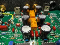
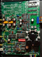
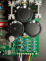
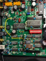
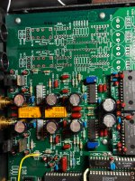
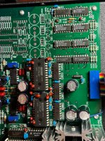
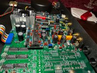
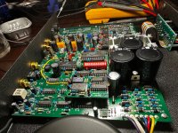
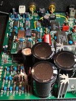
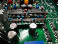
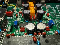
Hi res pics of the circuit board and power supply. Its not uncommon to have electrolytic caps start to degrade and fail after enough time. Sometimes the ends of caps will be bulged out a little, or there may be some signs of leaking electrolyte on the PCB near or sort of under the cap. There may be some other problems that are visually observable too. Also, it may be possible to take some voltage readings with a DVM. Sometimes power supplies are where the problems are. There can also be old, cracked, or corroded solder joints and or other connections.
Hi Mark,
Thanks for responding. Here are some pics. I don’t notice any residue or bulging caps.
Thanks for responding. Here are some pics. I don’t notice any residue or bulging caps.
Attachments
-
 IMG_1951.jpeg1.1 MB · Views: 22
 -
 IMG_1937.jpeg1.4 MB · Views: 25
 -
 IMG_1938.jpeg1.1 MB · Views: 25
 -
 IMG_1940.jpeg1.2 MB · Views: 22
 -
 IMG_1941.jpeg1.2 MB · Views: 20
 -
 IMG_1942.jpeg1.2 MB · Views: 20
 -
 IMG_1943.jpeg1.1 MB · Views: 20
 -
 IMG_1948.jpeg1.3 MB · Views: 21
 -
 IMG_1946.jpeg1.2 MB · Views: 19
 -
 IMG_1945.jpeg1.1 MB · Views: 17
 -
 IMG_1949.jpeg1.1 MB · Views: 20
 -
 IMG_1950.jpeg1.1 MB · Views: 22
There is a suspicious little spot on one cap at:

Otherwise, if you don't find any visible problems there are various options to consider trying next.
you could try adjusting all the controls and using all the various inputs and outputs to see if you can produce any change in symptoms.
You could take the board out and inspect the underside of it for visible problems.
You could get datasheets for IC components using part numbers on the top of the chips. Then measure their power pins with a DVM in both DC and AC modes to look for incorrect voltages.
You could do the same, except get an oscilloscope and look for AC waveforms that should be appearing at certain pins of various chips.
You could heat and or cool certain chips and or parts of the board to see if there are any thermal related problems.
And, whatever else anyone can think of. It can be a lot of work that may or may not pay off. Don't know what else to suggest at the moment.
Thanks for taking a look at the pics. The spot was just some residue that wiped off with alcohol. It's not from the cap.
I inspected the underside and don't see anything untoward. I did try the two types of inputs for which I have cables with the same ERR results.
I checked the electrolytics in circuit with an ESR meter. There are a couple with suspect readings, but you can't verify without pulling them out of circuit.
At 30 years old, I may just recap all the non-PS electrolytics and see where that takes me.
Well, I guess I need to trust my ESR meter more! Fixed! Cause: bad cap.
Today I was taking inventory of all the caps I needed to replace and putting an order together. I went back to look at a specific location to verify the specs, but it was difficult to read due to exterior discoloration I hadn't noticed previously, no bulging, just discoloration and a small amount of hidden leakage. This cap was also previously reading a high ESR (in-circuit). So I pulled it out and it still read defective! Awesome. I happened to have this value in my parts bin and popped in a replacement and now have good lock and no more errors!
I found this mainboard very difficult to work with, which reportedly uses “silver solder” or “wonder solder.” I have quality temperature-controlled equipment and still managed to lift a solder pad, though I'm way more experienced with normal old-school leaded solder and lower temps.
I think I will postpone the recapping for now or skip it all together.

Please try using the coax input...Please also using other digital source to find out if it's a problem with the DSP7000
- Home
- Source & Line
- Digital Source
- Enlightened Audio Designs DSP-7000 - constant ERR and weak output