The use of diodes for biasing might have suited the original output devices, but for my substitutes there is not enough control to keep them out of class AB (with all the problems that arises from that). The THD at 1kHz is 0.27% - not bad but not inspiring either.
I will substitute a Vbe multiplier for the diodes and report back. It might also be worth the effort to try a few other complementary pairs.
I am more than happy to buy a few more transistors or even fets.
BTW the Vbe multiplier you mentioned is a new one for me. Is this the type of thing you mean? - The VAS bias configuration? see circuit below.
Attachments
Hi farmerjack61,
With a few tweaks to the topology in your post #1, you will get quite
satisfactory, if not stellar, results.Actually, what I'm listening to right
now is very similar to yours.My advice would be:
1.Filter the supply rails to early stages with a small R and a big C
2.Filter the current through bias diodes of the CCS's as Mr. Self says
3.Use a proper Vbe multiplier for the output stage bias
4.Keep the gain somewhere around 30
5.Use appropriate transistors for the supply voltages (BD139 & 140 just won't cut it)
6.Use multiple output transistors at those supply rails (2 pairs min)
If you would like to experiment on the topology, I have PCBs housing 2 channels plus the power supply for smaller power outputs incorporating the points in my advice list.I can gladly send you samples if you mail me at
selim_ardali AT yahoo DOT com.
Happy soldering
Selim ARDALI
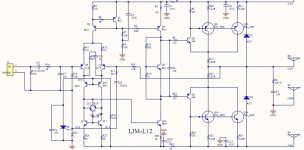
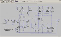
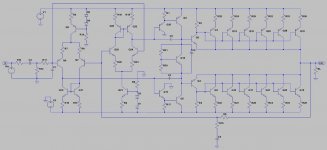
Here is the revised circuit, with Vbe multiplier. Things look a whole lot better. THD is now 0.02% at 220W into an 8ohm load. The amp needs 1.1V to drive it to full power, but any pre-amp can do that. The DC offset is -36mV. Changing R10 to 470ohm brings it right down to 2mV.
You will also note that I have done away with the doubled up diodes and resistors for the current sources.Doing so actually improves the THD numbers. I'm not quite sure why. Does anybody here know why?
The advice from selim about the BD139 and BD140 is spot on. In this circuit their collector-emitter voltages are almost 55V. According to their datasheets, they are rated at 80V, i.e. at nearly 70% of what the manufacturer calls 'absolute maximum.' That is a bit too close for comfort. The MJE340 and MJE350, rated at 300V, are ideal for this purpose.
Of course these results are only as accurate as the SPICE models used, and I have not checked that. Nevertheless, this circuit looks promising. There are still a couple of improvements that can be made. I will report back in due course.
Attachments
Last edited:
Hello again, it's 3am and I'm just about to go for a snooze!
Jeepers, you men have been working just as hard as me - I am truly indebted.
I have tried to do what I can by addressing the first three of Selim's suggestions, you will probably have a giggle when you see the simplistic approach I took to it. I am posting a shot of what I came up with today - I suspect it is a bit dodgey, but I will post it anyway so that you guys can see that I'm making some effort.
Attachments
Awesome, only two signal diodes now.
Substitute a pair of 669/649 or 4793/1837 for the 139/140
Use one 3281/1302 pair or two pairs of 4468/1695
No need to reply, I know your on to it.
Cheers.
Substitute a pair of 669/649 or 4793/1837 for the 139/140
Use one 3281/1302 pair or two pairs of 4468/1695
No need to reply, I know your on to it.
Cheers.
Uhm, shouldn't those two 2SC2240 npn transistors at the top left be pnp? In your original circuit it was correct. Replacing the two signal diodes with an LED is a good idea, but the transistor should stay the same.
The 2SB649/2SA669 are equivalent to the MJE340/MJE350 and will work well.
The 2SB649/2SA669 are equivalent to the MJE340/MJE350 and will work well.
Last edited:
And the resistors between V+ and the emitters should be 100-390 ohms, not 27k.
And for the question marks in the vbe multiplier, 1-2k on the upper resistor and a 1k pot in series with a 220-500 ohm resistor on the lower resistor
And for the question marks in the vbe multiplier, 1-2k on the upper resistor and a 1k pot in series with a 220-500 ohm resistor on the lower resistor
Last edited:
Just my 2 cents. 2sa970 and 2sc2270 are excellent transistors, but you might want use something a little heftier for your VAS transistor and current source, especially if you decide to increase the current in the VAS. Ive seen d668/b648 commonly used in consumer circuits but a lot of other possibilities. Just a suggestion. Good luck.
Third attempt to make an amp.
Hello Sreg' Thanks for the advice. I have replaced them with MJE340/50's, or I will use 669/648. Those MJE's are nice high voltage jobs and I can get them from West Florida Components - they only charge a few dollars to post them out.
I chose the A970/D2240 because they were high gain & low noise. But if they are going to get a bit hot under the collar they'll have to go.
Ingenius; my brother tried to kill me with some Rhubarb Wine last night and It looked completely workable to me then. Ha Ha Ha - Hangover now.
Tekko; Thanks cobber, Ingenius drew one up for me too - I really do appreciate all the work, and I will do the right thing by DIY in the next week or so.
I'll paste another drawing in here now so you can all have another look. I know it is still not right because I havent suffered any anxiety yet.
Here is what I am thinking; (Remember I'm a joiner)!
* If I poke too many capacitors on those rails will it alter the input and output impedance?
*Should I dump the 2200uF and his little mate - My power supply may be 2" or 3" away from this board (including the big filter caps).
* I only need about 20ma in the front end of the circuit. I pasted a 560 ohm 5W resistor in there, but that is burning up precious power. I have noticed that a lot of boards use a 68 ohm resistor - always seems to be a 68, even when the rail voltages are all different, I find that puzzling. Any suggestions?
* Short Circuit Protection; I have connected a voltage divider to the top of the output resistor, this arrangement applies 0.7V to the current shunt transistor's base once the output approaches it's limits, in effect shutting the output down. Is this a better set up than the rectifier diodes I have shown on the output - or might they be just as good and take up less room on the board?
* What are those little diodes on the collectors of the current shunt transistors for?
Please keep the ideas coming, we're almost there. I don't think I will need as much help with the trackwork or board layout as I have done some reading on that. Same for the grounding configuration.
Very happy man, very happy indeed. Bye for now, Phil
Attachments
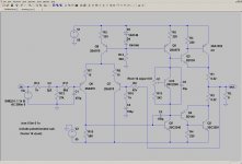
It's looking good, but I don't think you need to double up the MJE340/MJE350 driver transistors. The short circuit protection is always a good idea. I left it out on my schematic because I was in a hurry. Or too lazy to do the math, hehehe.
If you want to push the boat out a little further, there are a few more tricks. The differential pair can be improved by using a current mirror in the place of the 560 ohm resistor. Changing the VAS stage to a Darlington pair is also worthwhile. I'll post the schematic soon.
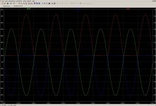
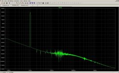
THD for 1kHz at 220W into 8 ohms is down to 0.0014% - quite something. Look at the FFT! The magic can probably be ascribed to the complementary feedback pair of the output stage. The downside of a CFP OS is said to be not as good as others, but I don't see any problems (yet).
If you want to push the boat out a little further, there are a few more tricks. The differential pair can be improved by using a current mirror in the place of the 560 ohm resistor. Changing the VAS stage to a Darlington pair is also worthwhile. I'll post the schematic soon.
THD for 1kHz at 220W into 8 ohms is down to 0.0014% - quite something. Look at the FFT!
The magic can probably be ascribed to the complementary feedback pair of the output stage. The downside of a CFP OS is said to be not as good as others, but I don't see any problems (yet).Attachments
Last edited:
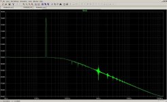
THD for 20kHz at 220W into 8 ohms is 0.083%. For 4 ohms at 415W it is 0.056%. Now to put back the short circuit protection...
2 ohms? Don't ask - asymmetrical clipping rears its ugly head. To overcome this seem to be beyond the capabilities of this circuit. Or mine. I have managed to modify the circuit to drive a 1 ohm load, but it becomes considerably more complicated.
2 ohms? Don't ask - asymmetrical clipping rears its ugly head. To overcome this seem to be beyond the capabilities of this circuit. Or mine. I have managed to modify the circuit to drive a 1 ohm load, but it becomes considerably more complicated.
Attachments
Gain equation
Re - janneman Post # 4
Just for clarity in the original posted circuit. Non inverting gain =
Av = 1 + R2 / R1 = 47k + 1k = 48k/1k = X 48 gain
If it was an Inverting amp, then janneman's calculation would have been correct.
@ farmerjack61
All the best with your efforts etc 😉
Re - janneman Post # 4
The gain of the amp is the ratio of that R to the 1k, so if you use 47k, you get 47 x gain.
Just for clarity in the original posted circuit. Non inverting gain =
Av = 1 + R2 / R1 = 47k + 1k = 48k/1k = X 48 gain
If it was an Inverting amp, then janneman's calculation would have been correct.
@ farmerjack61
All the best with your efforts etc 😉
Attachments
ZeroD,
your formula is confusing.
For non-inverting opamp
Av = 1 + [R2/R1] = 1 + 47k/1k = 1 + 47 = 48
or
Av = [R1+R2] / R1 = [1k+47k] / 1k = 48k/1k = 48.
For inverting opamp where in the above diagram the input is fed into the bottom of R1 and the ground is tied to the +IN labeled input.
Av =Rfb / [Rs + Rin]
All the series impedance between the source and the input resistor must be included inside those [] brackets. That impedance could be a resistor plus an output impedance plus a DC blocking capacitor.
Last edited:
Formula
Really !
Let me put it another way then.
In the picture i uploaded. Non inverting gain = R1 + R2 divided by R1
= 1k + 47k = 48k = 48 times gain 🙂
*
Re - Taking into acount impedance of capacitors etc etc.
I know what you mean, but my post was in response to janneman Post # 4 where he stated the gain was 47, when it's actually 48 in that example.
Originally Posted by AndrewT
your formula is confusing.
Really !
Let me put it another way then.
In the picture i uploaded. Non inverting gain = R1 + R2 divided by R1
= 1k + 47k = 48k = 48 times gain 🙂
*
Re - Taking into acount impedance of capacitors etc etc.
I know what you mean, but my post was in response to janneman Post # 4 where he stated the gain was 47, when it's actually 48 in that example.
THD for 20kHz at 220W into 8 ohms is 0.083%. For 4 ohms at 415W it is 0.056%.
Oops.
I just realised that my peak to RMS conversion was wrong. That should be 160W into 8 ohm and 300W into 4 ohm.
If anybody is interested, the circuit can be modified to be stable into 1 ohm as below. However, do not go building such a behemoth on my say-so. I know I wouldn't. Just to make sure nobody gets carried away, I'm not publishing any component values. Maybe later... 😛
Attachments
Hello again all. This is all very good news. So much interest in a simple little circuit. But since the Sheffield circuit was posted, it has been improved - out of sight by enthusiasts engineers and laymen (Provided the simulator tells no lies). Excellent.
I am away for a couple of days due to speaker building committments - back soon:
Here's where I am with the circuit but this is by no means finished and all the values are up for scrutiny.
Cheers and bye for now, Phil Elliott
I am away for a couple of days due to speaker building committments - back soon:
Here's where I am with the circuit but this is by no means finished and all the values are up for scrutiny.
Cheers and bye for now, Phil Elliott
Attachments
Many of the transistors have no emitter resistor !
Driver current @ ~3mA seems very low.
Hi there Andy, hope you were having a good day before I turned up!
I have attempted to address a few of the issues as seen in the attached photo.
I am also asking for advice from other members on four more issues as follows.
Hello again.
Andy has suggested more emitter-resistors so I have popped some extras in – without specifics I am only guessing. So which ones do I delete?
I put a pair of 4.7 ohms on the over-current protection pair located on the driver transistor’s bases. – (I drew them in there, but can easily delete them too!) – the collector current in this OCP-pair is only a couple of mA, but, what do YOU think?
Should I use the 100 Ohm resistors on the bottom of the two long arms of the diff? &&&& just to the right of those resistors we have put a C2240 to boof-up the D669 VAS transistor, does the 669’s emitter require a resistor? If so, what value?
The Vbe multiplier in this circuit uses a 2k2 pot for R1 & R2. So does this limit my options as far as biasing into class AB operation?
When I previously wrote ‘quiescent current 1mA’ what I meant was; 1mA is the minimum peak current under which the amp will operate in the A-class region, I came up with this figure by multiplying the base current of the driver transistor by a factor of 3.
Does the current mirror on the diff eliminate the need for adjustment of the current in the long arms – this might seem obvious to you but I’m not sure and don’t want to build a board and then discover that I needed a pot in the top of either arm.
My aim is to keep your design as simple as possible whilst making a few modifications to the original drawing where necessary, in order to achieve a good result.
Cheers, Phil E.
Attachments
- Status
- Not open for further replies.
- Home
- Amplifiers
- Solid State
- Engineer, help please - Neg. feedback/infilters