IMO, problemo numeral uno with most all of these "measurements" and subsequent explanations derived from such is the complete and arrogant lack of rigour in generating the data in the first place. Where is the experimental setup criteria defined? What about some sort of reference and/or control? Error analysis seems a distant cousin to reality displayed in the interpretations.
Some posters don't even take the time to understand that mispelling technical words looks incredibly foolish!!
Is it any wonder those with technical credentials are UNABL to take any of this stuiff seriously?
John L.
Some posters don't even take the time to understand that mispelling technical words looks incredibly foolish!!
Is it any wonder those with technical credentials are UNABL to take any of this stuiff seriously?
John L.
Regardless the fancy name they give it, the purpose and means have long been demonstrated in this forum for a long time. The reviewers must not have any experience in this technology....
GB2005001352 ACOUSTIC DEVICE & METHOD OF MAKING ACOUSTIC DEVICE
Commercially introduced as "Balanced Mode Radiator" by New Transducers Limited, uses annular masses for "modal balancing".
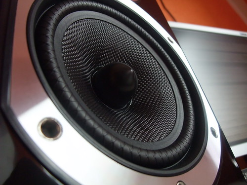
Here is a picture of an actual applicationYes, that is true. However, there are specific places to put things on any cone, dome or flat panel that are far more useful than others. This is true for the micro masses EnABL makes use of and considerably larger masses, such as those dlr is experimenting with and soongsc utilized in his dispersal of resonant nodes and the resultant patent.
Bud
http://www.audionet.com.tw/images/app/fck/image/00photo/2011TAA/64405.jpg
Last edited:
Where is the experimental setup criteria defined? What about some sort of reference and/or control? Error analysis seems a distant cousin to reality displayed in the interpretations.
John,
Having considerable training in the sciences (including one degree there), I would argue that such rigor is not absolutely necessary in order to demonstrate useful information in the real world (particularly the DIY audio world). If you're building bridges or sending people to the moon, then yes.
Furthermore, I doubt many here - including the technical ones - really understand error analysis in the sense in which it applies to statistics. How many know what heteroskedasticity is, much less know how to look for it and adjust their test methods for it? What about multicollinearity or autocorrelation? Or even more basically, how to derive error sets to do proper statistical analysis?
But does that mean nothing of merit can come of the testing and data that have been presented? If you think so, then feel free to ignore the thread.
Soongc:
Huh?Here is a picture of an actual application
http://www.audionet.com.tw/images/ap...1TAA/64405.jpg
Carl
Hey I am very good at that, lets do it in Dutch makes it a bit easier for me.😀Some posters don't even take the time to understand that mispelling technical words looks incredibly foolish!!
John L.
strawmen don't count
as usual, nothing of merit seems to be here worth testing, much less attempts to assign some form of legitimacy by calling this a technical thread.
likewise feel free to ignore my posts...😉🙄
discreditation via reductio ad absurdum doesn't work here. Nice try tho
John,
Having considerable training in the sciences (including one degree there), I would argue that such rigor is not absolutely necessary in order to demonstrate useful information in the real world (particularly the DIY audio world). If you're building bridges or sending people to the moon, then yes.
Furthermore, I doubt many here - including the technical ones - really understand error analysis in the sense in which it applies to statistics. How many know what heteroskedasticity is, much less know how to look for it and adjust their test methods for it? What about multicollinearity or autocorrelation? Or even more basically, how to derive error sets to do proper statistical analysis?
But does that mean nothing of merit can come of the testing and data that have been presented? If you think so, then feel free to ignore the thread.
Soongc:
Huh?
Carl
as usual, nothing of merit seems to be here worth testing, much less attempts to assign some form of legitimacy by calling this a technical thread.
likewise feel free to ignore my posts...😉🙄
discreditation via reductio ad absurdum doesn't work here. Nice try tho
...
Soongc:
Huh?
Carl
Hmm, the original link works fine for me, but the quoted link does not work.
Many websites do not allow "deep linking" from other websites directly to image files. You could download the image to your machine and attach it to a post here as a file attachment. (Assuming the image isn't copyrighted....) Or post a link to the page which the image is on.Hmm, the original link works fine for me, but the quoted link does not work.
AAAHHH thank you George, have been waiting a long time to see what you were up to. I assume that 7 bars works better than another number? Do they increase in number with a larger diameter? Do they suppress all loop back modes or are there still minor ones left in between the bars? Not that you have to answer any of my questions....
Bud
Bud
The number of bars, location, and angles all relate with the frequency range of interest. This is not a "cure all" solution though, just the last mile improvement. Note there is also three on the cap.
Warfedale is apparently on the same type of path. They made note that the indents on their surround were intentional, and for sonic benefit.
Regardless the fancy name they give it, the purpose and means have long been demonstrated in this forum for a long time. The reviewers must not have any experience in this technology.
Reviewers having "little experience" in this field seems quite usual IMO ...
Last edited:
Since there are no direct pictures of the phenomenon occurring on a driver for loudspeakers we have to infer. Take a look at the four short utube video's to see what this looks like on a flat vibrating diaphragm equal in area to a relatively large full range driver. Be sure to listen to the voice over and take note of the flow patterns depicted.
resonance - YouTube
resonance2 - YouTube
resonance4 - YouTube
resonance3 - YouTube
We have moved EnABL into a new era, version 2.0 for convenience and irrelevance. We utilize audible decay direction, from discrete and specific strikes on the driver surface, to find the "fences" that appear to be created and cause the steering of propagation from the driver into the air. The surmise is that these fences are created by transverse waves and that the ringing of these internal reflected waves creates some geometrical control over the steering mechanism, that is being called "loop back " for want of a better term.
When an EnABL pattern is applied on top of these "fence" circumferences the audible direction of the tap decay no longer changes. Uncontrolled diaphragms exhibit a change in decay direction from towards the voice coil to towards the surround, numerous times across a radial progression of taping from voice coil to surround. Once the EnABL patterns have been applied to the discrete circumferences all of the tap induced decay direction is towards the surround, across the entire diaphragm. The steering effects disappear and the diaphragms no longer exhibit any trace of lobes in either on or off axis positions. Instead an very uniform sound occurs across the swept angle of the diaphragm and smooth frequency roll off occurs further off axis.
These are empirically derived results. They have successfully defeated audibly nonuniform dispersion every time we have apply the patterns to the "fence" areas of different drivers. Because of the changes in decay direction we infer that there are loop back mechanisms at work, given the obvious demonstration of their existence in the above videos. Anyone willing to put in the time to learn how to discover the locations can reap the benefits regardless of how much verbiage is applied to debunking, so I invite you to the applications thread to learn how.
EnABL - Listening impressions & techniques - diyAudio
Bud
Enable Science?
Not just invisible, also inaudible | R&D Mag
Something about the experiments reported here may look familiar to followers of this thread.
Not just invisible, also inaudible | R&D Mag
Something about the experiments reported here may look familiar to followers of this thread.
so your point is that any sound originating from the center of this arrangement is inaudible to external listeners?
Doesn't seem to bode well for speaker efficiency.
Doesn't seem to bode well for speaker efficiency.
OOOEY! I CAN'T WAIT to see how that research gets taken out of context, spindled, and mutilated!
Might be that just some of the "sound", perhaps that created by transverse waves resonating, is no longer audible.
There, the first spindle and mutilation and entry point for "filching for the cause"
There, the first spindle and mutilation and entry point for "filching for the cause"
except that the enabl patterns bear no resemblance to meta-material patterns, not to mention the axis problem. Exacting details are what counts here... show some math or let it rest,please... this IS the technical thread, not the speculation thread
Last edited:
- Home
- Loudspeakers
- Multi-Way
- EnABL - Technical discussion