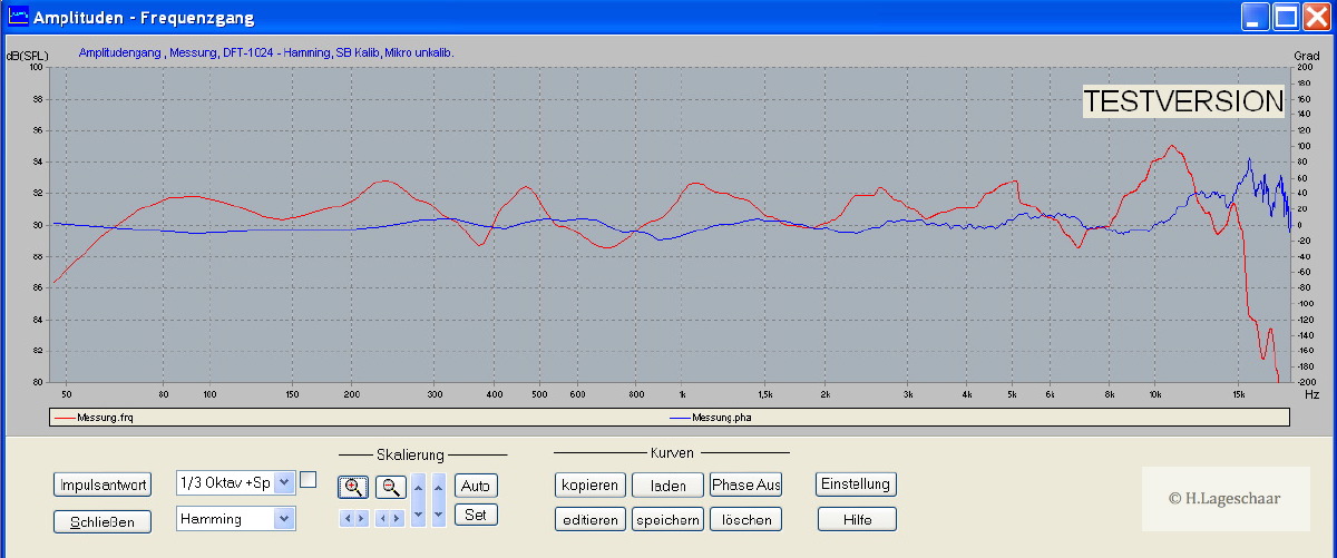
Sure. I'm leaving for the long weekend soon, so hopefully before I leave. I don't know much about measurement. So I appreciate the help. Hearing what all of you are saying makes me wonder if I botched the whole thing. I thought the FR looked correct (a little messy) but didn't pay much attention to the impulse. What does the impulse even tell you? How controlled the cone is?
Last edited:
Actually, the impulse is how the frequency response is derived. The impulse response is either measured directly or derived from an MLS response, then Fourier transformed to get frequency response. The inverse can also be done- both time domain and frequency domain have the same information embedded in them.
While that's true, I think the question could also be more accurately re-framed as "what useful information can be ascertained by looking directly at the impulse response visually instead of transforming it into other representations such as frequency response, cumulative spectral decay, etc" To which I'd say in many occasions, "not much".Actually, the impulse is how the frequency response is derived. The impulse response is either measured directly or derived from an MLS response, then Fourier transformed to get frequency response. The inverse can also be done- both time domain and frequency domain have the same information embedded in them.
Sure, certain types of responses can have nice text book impulse responses that you can interpret somewhat by eye, but as soon as you have "complicated" stuff going on at the high frequency end such as multiple cone resonances, it quickly gets to the point where you can't make much sense of the raw impulse response, or the changes that selective damping may be making.
For studying cone resonances such as those that EnABL is attempting to address I find the most useful measurement by far is cumulative spectral decay, studied in conjunction with the frequency response. (Frequency response by itself is not enough information)
When doing my own driver damping experiments I've found a very good correlation between the sound of resonances, and how they look visually in a CSD, once you get a feel for the correct amplitude and time scales.
Although I look at the impulse response out of interest, when it comes to breaking down driver flaws individually to analyse and address them I don't think visual analysis of the raw impulse response is actually all that useful.
YMMV.
Last edited:
No one mentions the use of phase in thier results, I find it very useful in fine tuning the XO point As you can see in my monitor-xl topic, I plotted the minimum phase a abrupt change in phase is equal to distortion.
So when you got distortion you got abrupt phase shifts.
Here i measure the two way near field to discriminate other influences. And the microphone between the woofer and horn this to have the same travel distance you see a smooth minimum phase bleuline.
Here both speakers on mls signal microphone on my listining position so room reflections take place still a very smooth minimum phase 100-10000Hz.
It is a shame people can read the plots I show there then they would know how great it measures. You have to done some measurements and see result before you can compare what I show there.
Last edited:
Simon, I'd disagree a bit. Looking at the time domain, it's easier to spot reflections, and from their time, to then make good guesses as to their origin. A simple example is the first floor reflection, which we will usually gate out, but thinks like cabinet cavity resonances, diffraction, reflections transmitted out the cone, and the like can also be spotted, identified, and fixes can be validated.
Simon, I'd disagree a bit. Looking at the time domain, it's easier to spot reflections, and from their time, to then make good guesses as to their origin. A simple example is the first floor reflection, which we will usually gate out, but thinks like cabinet cavity resonances, diffraction, reflections transmitted out the cone, and the like can also be spotted, identified, and fixes can be validated.
I completely agree about using the raw impulse response to find reflections such as floor reflections, baffle edge reflections, cavity back reflections and so on. That's certainly the best use of looking at the raw impulse response, and obviously we need to look at the impulse response at the very least to gate out reflections originating from beyond the confines of the cabinet when taking measurements.
But when applying damping treatments to a cone it's resonances we're trying to control not discrete reflections, and here CSD is king. Although everything you need to know is encoded within the impulse, the best way of "decoding" it visually depends on what you're looking for...
A frequency response graph can't distinguish between resonance induced peaks/dips and reflection induced peaks/dips, whilst a visual impulse response will only show "obvious" resonances, and only be interpretable if there aren't too many different ones occurring at once.
A CSD will pick out and make obvious even the tiniest low level resonance, and allow you to examine every resonance independently and in detail regardless of how many there are at once in the total response. So for damping a cone it's the right tool for the job.
Last edited:
Agreed, for looking at cone phenomena, I'd want to use other measures. Complex impedance (Heyser plots) for sure, frequency response, polar response, waterfall, Wigner. I was being more general- sorry for the poor communication.
I was impressed by how clearly migeO's wavelet graphs showed reflections arising only on the cone. Very much like a set of block prints stamped out in time, showing very discernible patterns repeated.
Bud
Bud
I curious as to whether anyone had investigated fiber rubbing in these cases.
Hi,
some thoughts on this, because a woven structure may have
interesting properties.
The friction between the fibres may introduce a large amount of
damping without the mass increase a dampening coat would
introduce on a paper cone e.g.
Furthermore i would expect a weave to have slightly different
wave propagation speed in different directions (anisotropy) which
may contribute to (local) diffusivity, especially since those weaves
don't seem to be spread out axial symmetrically over the membranes
shape.
I imagine it could be tricky to get the amount of damping fairly
independent from the level of excitation ...
Rather slow wave propagation, high damping, diffusivity ...
would be ingredients for a rather "silent" cone material ?
Regards
Last edited:
It's interesting to discover how different types of data presentation will reveal different information. CSD presented in the traditional means present data within a specific range after the beginning of the sliding window, Wavelet transforms present spectrum within a small sliding window. In practice, if we can get Wavelet Transforms in a better resolution, then we can diagnose problems more associated with the driver.
... if we can get Wavelet Transforms in a better resolution, then we can diagnose problems more associated with the driver.
As for now, I do not think there is *any* analysis that goes beyond the resolution of PBW (Packed Burst Wavelet) analysis method, regarding both: time and frequency
http://www.diyaudio.com/forums/ever...-giant-leap-maturizing-audio.html#post2616725
but you are always welcome to point me there *if* there is
🙂
Michael
Hi,
some thoughts on this, because a woven structure may have
interesting properties.
The friction between the fibres may introduce a large amount of
damping without the mass increase a dampening coat would
introduce on a paper cone e.g.
In a recent StereroMojo review (with CSD analysis) of the Audioengine P4 speakers, it showed that the weaved cone they use may be a very effective means of maintaining the cone integrity. The weaved woofer/mid consists of a Kevlar woven glass aramid composite with rubber surrounds.
Audio Engine P4 Speaker Review
An externally hosted image should be here but it was not working when we last tested it.
The P4 cumulative spectral decay or CSD plot is very good. The response drops like a rock with no apparently ringing or overhang. Very nice indeed. I have consistently found that speakers with clean CSD plots have a tendency to sound the least fatiguing and are the most resolving if everything else remains equal. I think this explains how they can get away with a slight rise in the treble response without fatigue. This is a seriously good CSD plot.
Dr. Peter Fryer on "woven fibre cones" and behaviour of cones when leaving the
whole body motion at higher frequencies:
Bowers & Wilkins - Kevlar
... audio interview
"Maintaining the structural integrity", meant as "keeping the cone's shape in a whole body motion
even at higher frequencies", is even impossible with woven fibre cones.
An advantage may be seen in a tendency to exhibit cone resonances of lower Q and hopefully
(with elaborated design) to come closer to "non resonant" behaviour even when breakup occurs.
Regards
Last edited:
I mean quality resolution within 1ms, probably in 0.02ms time frames. Currently I look at CSD in 0.37ms range with 36 slices which is the best SoundEasy provides for a 96KHz sample rate.As for now, I do not think there is *any* analysis that goes beyond the resolution of PBW (Packed Burst Wavelet) analysis method, regarding both: time and frequency
http://www.diyaudio.com/forums/ever...-giant-leap-maturizing-audio.html#post2616725
but you are always welcome to point me there *if* there is
🙂
Michael
The range shown is barely 22db. The vertical scale is only 25db and the peak response does not go full scale. The graph hides more than it shows. This doesn't address the low end, that is rolled off to begin with, so the peak/minimum on the graph is very low, 15db or less, yet the decay is still long there.An externally hosted image should be here but it was not working when we last tested it.
The P4 cumulative spectral decay or CSD plot is very good. The response drops like a rock with no apparently ringing or overhang. Very nice indeed. I have consistently found that speakers with clean CSD plots have a tendency to sound the least fatiguing and are the most resolving if everything else remains equal. I think this explains how they can get away with a slight rise in the treble response without fatigue. This is a seriously good CSD plot.
If a driver's decay is to be analyzed, you have to see a significant amount of db scale at any frequency analyzed. That CSD doesn't show nearly enough.
Dave
Soft diaphragm drivers normally have good CSD performance, but the more damping the material itself provides, the more lower level detail is lost.
...
If a driver's decay is to be analyzed, you have to see a significant amount of db scale at any frequency analyzed. That CSD doesn't show nearly enough.
Dave
I am definitely on the same page concerning that plot ...
Regards
Soft diaphragm drivers normally have good CSD performance, but the more damping the material itself provides, the more lower level detail is lost.
I can follow your statement from own auditive impression very well,
when listening to some designs.
But i also fear that, depending on progamme material presented, some
listeners will judge a system that rings and has some high Q resonances as
"more detailed" ... especially in the presence and/or brillance range.
I would prefer systems with proper CSD at first place, but i also feel
that there is "something wrong" with certain (internally) high damped
cone designs.
My suspect is a damping behaviour which is nonlinear. It may
contribute to an inconsistent and level dependent auditive impression
of some cone designs.
If one manages to implement "true" - purely resistive - damping behaviour
independently from the level of excitation, then damping should not
cause problems on the auditive side IMO.
Damping of a cone's "whole body motion" by the voice coil due to back
EMF is commonly not under suspicion to have negavite effects on
the auditive impression. This may be because with proper motor design
that kind of damping is fairly independent from the level of excitation.
The problem may not be in the internal damping of the cone, but
in the difficulty of manufacturing a membrane with "close to ideal"
(level independent) damping.
Regards
Last edited:
True, it takes lots of listening to figure out what is right and what is wrong. Most the time I try to listening while I'm doing things, then switch around to see what I feel over a period of time. It's amazing that what initially perceived as not so much difference can become big differences. Hi Q resonances generally will cause an instrument to shift in image location or focus as it goes through those specific notes.
More confusing is what causes things to be wrong or right along the chain of equipment. Fix one place, and hear some new problem, was the problem originally hidden or is it really new? Level dependent sound changes are also really hard to figure out.
Any damping material applied really should be done without creating increased loss between the VC and the radiating surface that pushes the air. In more general terms, we want to damp the ringing without damping the onset transients.
Motor design is also an interesting thing. But I'd always want to prevent back EMF from entering into the feedback loop of amplifiers as much as possible.
Last edited:
I seriously doubt that there is significant non-linear distortion originating in the diaphragms of most drivers, if not all. Linear distortion, sure, we see that all the time in the typical raw frequency response and in typical linear distortion measurements.I would prefer systems with proper CSD at first place, but i also feel that there is "something wrong" with certain (internally) high damped cone designs.
My suspect is a damping behaviour which is nonlinear. It may
contribute to an inconsistent and level dependent auditive impression
of some cone designs.
There's an easy way to determine how much total non-linear distortion exists as well, testing. This will include all forms of non-distortion such as from a motor, spider, etc., likely to be far more significant as a percentage. Keep the total non-linear distortion down and it isn't important whether it's motor distortion or something else.
The problem I have with this is that using perception to determine the source of the reason for that perception is not reliable. I always felt that the better doped paper (e.g. Scan Speak) midrange sound better than any others. They are reasonably stiff, have good internal damping and excellent FR with good or excellent distortion characteristics. There's nothing to show that they have "lack of detail", other than has been mentioned, they don't have the resonant behavior, linear distortion, that can exacerbate both the linear and non-linear behaviors in the harmonics. This may be why many prefer hard diaphragms, they like the supposed "detail" this can provide.
Personally, I think that this may also be at work in the Enabl situation. Change the upper resonances (they largely are not eliminated as we've seen) and the perception changes due to change in both the upper FR and the harmonic distortion that they contribute. It's largely based on perceptions and expectations.
This sounds like speculation to me. If anyone has reference to data to back it up and that shows differently, I'd be interested in seeing it.The problem may not be in the internal damping of the cone, but
in the difficulty of manufacturing a membrane with "close to ideal"
(level independent) damping.
Dave
- Home
- Loudspeakers
- Multi-Way
- EnABL - Technical discussion