Thanks for updating us on your seemingly aggressive plans for testing.
Its what i do, ppl here want objective results,personally i could care less about the "impression" factor that some appear to dwell upon in this topic.
It all comes down to root cause and effect and the defination of the actions. Once you define the actual actions then sometimes you modify the physics/math to adapt to the actual results. We can postulate till the end of time, but with established results the modification for greater performance is possible.
ron
BudP said:As a question. Do you think that an ink jet print head of any sort could be used with robotics to apply a printed pattern? I know exactly nothing about them or the inks they use, or could be corrupted into using. P.Pecker says he has a friend who can do the arm robotics. Where might I begin to look for information?
Bud
Bud,
Something like this should work.
(This is my first post in this thread, but I've been lurking since page one!)
Bill
Cal Weldon said:small Fostex (126?) in the mini fonken box
FE127e & FE127eN in Fonken
http://www.planet10-hifi.com/fonken.html
dave
Anyone keeping track of the score?😀Cal Weldon said:Bud and all,
It took months of hearing about it and close to 2000 posts in this thread before I was able to step in and say I have now had a chance to listen. It was the small Fostex (126?) in the mini fonken box seen here near the bottom. I was very surprised by lack of relief to the pattern. Barely discernible dashes.
http://www.diyaudio.com/forums/showthread.php?postid=1412351#post1412351
I am not interested in the technical jargon but here is what I heard:
Like so many others that have tried to describe what the difference is, all I can tell you is this: It's not easy to describe it other than to say it sounds less like a dynamic cone speaker. By that, I simply mean that the sounds we have become accustomed to and have accepted for eons seem to have been reduced. It was less cluttered sounding. It now sounds less like a 'speaker' and more like a pure transducer. To try and describe it further than that is fruitless until you have listened also.
Thank you Bud, I am glad I finally got to weigh in on the issue.
I knew this would happen.😉
But now this only begins a new round of improvement in other areas of the reproduction chain. You will truly be able to hear improvements whenever they occur.🙂
Is this the laser based measurement that was talked about? Klippel? Bandwidth of laser pickup?ronc said:1: Set up a 3 axis stepper motor drive system to follow the contour of the cone.(Done)
2: Had the dimensional lab establish the driver cone contour using a CMM.(This data will be programmed in as G Code in .001" steps and recorded)(Done)
3 Designed a holding fixture to allow the same tangential response between the laser/detector. (to be built by the machine shop).
All tests will be run on a stock 166 vrs a Dave(planet 10) supplied EnABL equipped 166 on a 24 " square baffle.
All tests will be performed in an acoustically dead enclosure of dimensions of 34"H x 18 D" x 30" W. Tests on the enclosure shows > 64 Db loss @ 1000 hz. This is used to prevent outside influence.(Unit i used to do vibrational analysis)
Any critique , please step up to the plate.
ron
It was less cluttered sounding. It now sounds less like a 'speaker' and more like a pure transducer.
To me, now as i stand back and examine the actions, it should.
ronc said:1: Set up a 3 axis stepper motor drive system to follow the contour of the cone.(Done)
2: Had the dimensional lab establish the driver cone contour using a CMM.(This data will be programmed in as G Code in .001" steps and recorded)(Done)
3 Designed a holding fixture to allow the same tangential response between the laser/detector. (to be built by the machine shop).
All tests will be run on a stock 166 vrs a Dave(planet 10) supplied EnABL equipped 166 on a 24 " square baffle.
All tests will be performed in an acoustically dead enclosure of dimensions of 34"H x 18 D" x 30" W. Tests on the enclosure shows > 64 Db loss @ 1000 hz. This is used to prevent outside influence.(Unit i used to do vibrational analysis)
Any critique , please step up to the plate.
ron
What kind of signal are you planning to apply to the driver terminals? A true impulse first comes to mind.
How will you capture the data for presentation? That is, what will we be able to see with regard to results?
What kind of pattern across the diaphragm will you use and how much of the diaphragm surface will be covered?
Dave
BudP said:As a question. Do you think that an ink jet print head of any sort could be used with robotics to apply a printed pattern? I know exactly nothing about them or the inks they use, or could be corrupted into using. P.Pecker says he has a friend who can do the arm robotics. Where might I begin to look for information?
Bud [/B]
Comments from an analytical chemist who has worked on studying failed printer heads (typical of home type printers.)
1) Ink jet printers are designed to produce extremely tiny droplets in order to make high quality graphics. This isn't what you need in your EnABL pattern. All you need is decent edge sharpness on the blocks or dots.
2) The tiny channels in ink jet print heads are easily plugged by extremely tiny particles, so the requirements for the ink are very stringent. Why make trouble for yourself by using an application system that imposes requirements that vastly exceed what you need in the end?
3) There are different types of inks, ranging from water & organic solvent based to the waxy (no solvent) inks in Xerox's Phaser printers. You need to be careful of the properties of the 'dried' (or cooled or cured) ink. Many inks lose their solvent but are never what I would call dry. And then they must be compatible with the overcoat layer. E.g. Waxy material will repel most paints.
4) There is already good technology for applying ink & paint to a wide variety of surfaces--from making designs on t-shirts to custom printing on pens. Why re-invent the wheel?
Just my thoughts.
Jim
Looks like a pretty good tool.lousymusician said:
Bud,
Something like this should work.
(This is my first post in this thread, but I've been lurking since page one!)
Bill
🙂
Hi Cal,
So.... what is an Altec 210? I am truly ignorant, not uncaring. I am also interested in the project. As I suspect others will be.
Bud
So.... what is an Altec 210? I am truly ignorant, not uncaring. I am also interested in the project. As I suspect others will be.
Bud
Jim Shearer,
Ignorance upon my part. I actually have a Walnut shell, with very clear printing done on its outer surface. But that doesn't really help me understand how to print on a surface that is curved in two vectors. And, it doesn't provide a phone number I can call, to talk to someone for whom that question isn't really one at all.
As always, the devil is in the details and I need to find the person for whom these particular speaker details, are not a bedevilment.
Got any suggestions? They will be welcome. And thank you for what you have already provided.
Bud
4) There is already good technology for applying ink & paint to a wide variety of surfaces--from making designs on t-shirts to custom printing on pens. Why re-invent the wheel?
Ignorance upon my part. I actually have a Walnut shell, with very clear printing done on its outer surface. But that doesn't really help me understand how to print on a surface that is curved in two vectors. And, it doesn't provide a phone number I can call, to talk to someone for whom that question isn't really one at all.
As always, the devil is in the details and I need to find the person for whom these particular speaker details, are not a bedevilment.
Got any suggestions? They will be welcome. And thank you for what you have already provided.
Bud
BudP said:So.... what is an Altec 210?
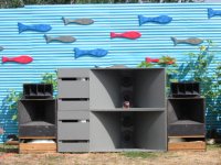
Hi bud, I'm just having a little fun with you. The 210's are the big ugly gray things in the middle. 😉 If you need a reference, that's a 20 oz mug of beer.
Which horns are you referring to?
Attachments
BudP said:Hi Cal,
So.... what is an Altec 210? I am truly ignorant, not uncaring. I am also interested in the project. As I suspect others will be.
Bud
Bud - See this http://www.voiceofthetheatre.com/images/LF.horns.1.jpg
lousymusician,
Thanks for that. I need one of those. Who cares about speakers! A toy like that to play with, would easily see me through the last decade or so of this life.
Seems like it would need a couple more axis definitions though, and maybe a turret base with infinite indexing and maybe a laser interferometer for feed back, for position control... maybe binocular laser interferometers..... see, SEE, this is why, eventually, 1000 year old calligraphy pens end up looking like a tall cool drink of water, to my overheated brain....
Bud
You know folks, I wrote a little note a few, maybe hundred by now, posts back, thanking everyone for contributing. I left one guy unmentioned. Mostly because so many of us in so many different threads, have benefited from his magical ability to provide a meaningful link, that answers a question and provides information on a couple of dozen more, every single time......
HOW DO YOU DO THIS THOMAS?!!!!
Thank you C2C, I am beginning to understand that C2C part, by the way. I think we need another category in this forum...Oracle. You wouldn't be the only one, but you will certainly be one of the most asked.
Bud
HOW DO YOU DO THIS THOMAS?!!!!
Thank you C2C, I am beginning to understand that C2C part, by the way. I think we need another category in this forum...Oracle. You wouldn't be the only one, but you will certainly be one of the most asked.
Bud
What kind of signal are you planning to apply to the driver terminals? A true impulse first comes to mind
A single square wave in a positive then a negative of equal amplitudes.
How will you capture the data for presentation? That is, what will we be able to see with regard to results
Thats up to the techs. I dont get into that stuff.
What kind of pattern across the diaphragm will you use and how much of the diaphragm surface will be covered?
Its basically a spherical produced wave from a round radiator with the start of the scan being at the edge of the wizzer. So the scanning unit is designed around a horz scan across the cone.
Only problem i have seen with the focused holding fixture is the wizzer causing a loss of scan due to the shadow effect near the wizzer towards the outside of the cone.
I will be going to a monocromatic light source instead of a laser to increase the amplitued. ( a little of the old inverse square law here.)
I still have to work out the static values of the recieving sensor/vrs amplitude to determine which emmiter will work best.
ron
Hi Bud! Thank you for the kind words.
Actually C2C means "choose 2 change" - a little ideogram that helps keep me on track in this life. 😀
Actually C2C means "choose 2 change" - a little ideogram that helps keep me on track in this life. 😀
Sample rate is also an issue. Based on data I have seen related with the EnABL type effects, it might not even get much of the frequency where the EnABL process changes. But it's still good to see what results from this measurement.ronc said:What kind of signal are you planning to apply to the driver terminals? A true impulse first comes to mind
A single square wave in a positive then a negative of equal amplitudes.
How will you capture the data for presentation? That is, what will we be able to see with regard to results
Thats up to the techs. I dont get into that stuff.
What kind of pattern across the diaphragm will you use and how much of the diaphragm surface will be covered?
Its basically a spherical produced wave from a round radiator with the start of the scan being at the edge of the wizzer. So the scanning unit is designed around a horz scan across the cone.
Only problem i have seen with the focused holding fixture is the wizzer causing a loss of scan due to the shadow effect near the wizzer towards the outside of the cone.
I will be going to a monocromatic light source instead of a laser to increase the amplitued. ( a little of the old inverse square law here.)
I still have to work out the static values of the recieving sensor/vrs amplitude to determine which emmiter will work best.
ron
ronc said:What kind of signal are you planning to apply to the driver terminals? A true impulse first comes to mind
A single square wave in a positive then a negative of equal amplitudes.
How will you capture the data for presentation? That is, what will we be able to see with regard to results
Thats up to the techs. I dont get into that stuff.
What kind of pattern across the diaphragm will you use and how much of the diaphragm surface will be covered?
Its basically a spherical produced wave from a round radiator with the start of the scan being at the edge of the wizzer. So the scanning unit is designed around a horz scan across the cone.
Only problem i have seen with the focused holding fixture is the wizzer causing a loss of scan due to the shadow effect near the wizzer towards the outside of the cone.
I will be going to a monocromatic light source instead of a laser to increase the amplitued. ( a little of the old inverse square law here.)
I still have to work out the static values of the recieving sensor/vrs amplitude to determine which emmiter will work best.
ron
This doesn't sound like it will produce anything useful. If you hit the driver with a single pulse (or cycle) you have a choice: 1) scan a single cone position in time to get the transient behavior at that point. 2) Scan across the driver in which case you will have the deflection of the cone at varying radials point and at varying instants in time. Two isn't of much use at all. One doesn't tell you anything about the cone behavior except at a single point. If you want to do this correctly you need to do 1 repeatedly at many radial and circumferential positions to map out the transient behavior of the cone surface. An impulse would be the better stimulus since it will contain greater high frequency energy. I would suggest radial and circumferential spatial increments of about 1/10 the wave length of the highest frequency of interest. For a 6" diameter cone this would mean 45 radial points by 275 circumferential point (12,000), but since bell modes usually are at lower frequency you could probably cut the number of circumferential points down to 30 or so (1300 points total). You could probably get away with 20 radial points so we’re down to 650 total points. This will also require sync of the data acquisition system with the stimulus. The result would be that you would have an animation of the cone response to a pulse which could then be viewed at what ever play back speed desired.
Most laser scans of drivers I have seen have been at a single frequency to map out the cone standing wave resonances. See below.
An externally hosted image should be here but it was not working when we last tested it.
I actually have a Walnut shell, with very clear printing done on its outer surface. But that doesn't really help me understand how to print on a surface that is curved in two vectors. And, it doesn't provide a phone number I can call, to talk to someone for whom that question isn't really one at all.
As always, the devil is in the details and I need to find the person for whom these particular speaker details, are not a bedevilment.
Got any suggestions? They will be welcome. And thank you for what you have already provided.
Bud [/B]
I don't happen to know anyone's phone number off the top of my head, but if I really wanted to know I would try two things:
1) check on the web--places like Wikipedia come to mind;
2) I get sample advertising pens w/ my name & info on them. Look for a place that does that sort of thing & give them a call. If they don't do it in-house, maybe they still know about the process.
Good Luck!
Jim
- Status
- Not open for further replies.
- Home
- Loudspeakers
- Multi-Way
- EnABL Processes