huh?
>>Are you joking, its very basic.
I'm sorry, this evasion of questions has become mindless...
My 40+ years of engineering experience tells me it's time to exit this discussion.
(now bowing out to the truly enlightened members)
John L.
>>Are you joking, its very basic.
I'm sorry, this evasion of questions has become mindless...
My 40+ years of engineering experience tells me it's time to exit this discussion.
(now bowing out to the truly enlightened members)
John L.
Here is my opinion, as severely modified by a person much smarter and infinitely more practical than I am, my wife.
First point. This is not an OR situation, it is an AND situation. The piston model is very complete and quite able to access the performance of a driver that is pistonic. This means voice coil motor strength, surface area of the emitter and the resulting compression wave in the air. The problem arises exactly where Beranek pointed to, in the time to compression wave creation energy coupling device, the diaphragm.
second point. The process ronc is describing is the activity of a compression wave transforming energy into a diaphragm, i.e. an explosion in a containment vessel. This energy transform occurs at the layer of materials where air interpenetrates the diaphragm of the pressure vessel. The most efficient transformation of energy to this diaphragm occurs when this boundary layer is undisturbed by turbulence. This is a laminar boundary layer.
Third point. The diaphragm of a loudspeaker is non pistonic except for one frequency. This frequency is determined by all of the parameters involved, including the area being charged on both sides of the diaphragm. The voice coil is obviously pistonic, but the efficiency of its direct transformation of motion into resultant compression wave is so low that we have to add a larger surface, to allow a greater area for this transformation. The problems occur when the energy from the pistonic voice coil, have to transform into transverse waves to move through the diaphragm to inform the edge it must move also. This occurs because the stiffness to mass ratio is not infinite. This additional body cannot move as a piston because the extremities cannot be informed of the voice coils movement and a bending wave is induced. There is an interval of time inherent in this activity.
Fourth point. Bending waves are destructive to the medium they move within. ronc's point here is that if you allow the energy from an explosion to enter a diaphragm, of in this case, a containment vessel, through a laminar boundary layer, this transformation of energy will be destructive, as a transverse wave that rings until it finally overcomes the material strength, in some local spot, and the diaphragm ruptures. If there is turbulence at the boundary layer, a laminar condition cannot arise, and the diaphragm will tolerate a greater amount of energy in the compression wave.
Fifth point. This very same function is at work in an EnABL'd diaphragm. The EnABL pattern causes turbulence in the boundary layer. This is obvious if you put the pattern into a wave simulation program. The pattern blocks stand about 0.015 above the surface of the diaphragm. This is a very tall artifact within the boundary layer. These pattern blocks force the energy transformation juncture to traverse them, by going over them and create turbulence by also forcing the transverse wave to go through them. This entire process "stacks” the wave up, just as a tsunami rises out of the surrounding water, at a beach. This is energy stacking, that is the function creating the transverse wave, being displaced vertically, but not by 20 or 30 feet, just by .0015 inch.
Sixth point. Having forced the transverse wave to a greater vertical height, the transformation juncture is also forced up out of the boundary layer and because of the turbulence created by the pattern blocks in this boundary layer, neither the extended transverse wave height, or this juncture can easily reenter the diaphragm. They will over some distance traveled, reenter the diaphragm and the turbulence will subside and a laminar condition will once again prevail. Entropy demands this be so. To prolong this period of reentry a coating that makes the boundary layer less rough and thereby have a lower friction coefficient is applied. This, to a degree offsets the major entropy mechanism, in the boundary layer.
Seventh point. I refer to Soonsgc's now infamous phase change plots not to attempt to disprove piston theory, by attacking the Hilbert Transform. Instead I am following the same thought both he and John K spoke of. The measurements showed a trend. The trend was that the effective distance between diaphragm and microphone had to be getting shorter. This was the only explanation that could be possible. John K, not having run the experiment himself, worried that is showed an actual physical change in microphone distance.
Soonsgc responded that this did not happen, that the testing of the application of additional rings of EnABL patterns, was done without moving either device. His application tool allowed him to apply the patterns without disturbing the relationship between diaphragm and microphone. His conclusion was that the juncture of transverse wave, which his test suite could not "see", and energy transformed into a compression wave, which his test suite could "see", had lofted off of the original surface and on top of the turbulence, which acted like ball bearings, just as it does when any laminar boundary layer is disturbed by turbulence.
Eighth point. The transformation juncture between transverse wave and the compression wave it creates, acts just exactly like the compression wave event when an explosion occurs and it’s pressure wave contacts a pressure vessel wall. As long as there is turbulence in the boundary layer, less energy can enter, or in the case of the speaker diaphragm, reenter the surface where the boundary layer exists. In the case of the speaker diaphragm the extended height transverse wave is feeding the creation of the compression wave. This event is aided by there being a reduction in friction in the boundary layer, due to turbulence in the boundary layer and the conformal coating smoothing the surface imperfections of the diaphragm.
Tenth point. None of these points indicate that the piston model is wrong. They only add an additional mechanism of better use of the diaphragm. This through moving the juncture between transverse wave and compression wave completion, began by the voice coil piston, out of the high friction laminar boundary layer, adding turbulence to the boundary layer and keeping this turbulence, and lofted juncture, across the entire surface of the diaphragm. The final EnABL pattern reinforces this lofting of the juncture and extends the turbulence beyond the diaphragm, through the surround and over the basket surface. The physical edge of the diaphragm is no longer an impediment to the compression wave, because it is riding on the turbulent boundary layer and so is not effected. What remaining energy is left in the transverse wave, is again lofted and “steps over” the end of the diaphragm, through the surround and over and around the basket surface, continuing to emit energy into the compression wave. Ideally the juncture is broken at the final edge of the basket surface. If another EnABL patterns is added here this separation occurs without diffraction lobes, which are also compression waves, being created.
I am indebted to all of you for forcing this examination. And I am especially indebted to those individuals who showed me that there were mechanism’s at work, but they were not working exactly as I had originally envisioned them to. And, of course to my wife for smacking upside the head and saying “idiot, this is AND, not OR”, no wonder they are upset with you! So, in addition to gratitude I offer my apologies for creating unneeded turbulence, in this boundary layer.
I am sorry Bud, but none of that makes any sense to me. I'll bow out of the discussion at this point.
MJK said:I am sorry Bud, but none of that makes any sense to me. I'll bow out of the discussion at this point.
I agree. Absolutely none of that makes any sense whatsoever.
Dave
All efforts for rational scientific reasoning are wasted here.
The only way to debunk this is by doing it, hearing either no difference or no improvement and then reporting the results.
I have tried it, and it made no difference that I could hear.
All of the faithful should be tested for their listening acumen. I posted this thread a few days ago.
Surely, Enabl will allow the listener to distinguish a lower level of distortion.
Assuming air speed of 344M/Sec, at 10KHz half wave length is 17.2mm, the point of highest flow speed is midway on the node. I'm sure you have more expertise to do the FEA calculation than I do to calculate the rate of change in airflow. It is not how far the air moves that matters, it's how fast the flow is, especially over the pattern.MJK said:
In real numbers, how far do you think the air moves for a typical driver vibrating at 1000 Hz or 10000 Hz with a 1 watt input? The air moves back and forth with no net displacement and I have to believe the absolute motion is very very small.
Theoretically the pattern works best on soft diaphragms. At least based on the materials discussed in this thread. If was made clear quite early in this thread or some reference sites that the pattern material should be such that the soundspeed must be greater than the cone material soundspeed. So if just blindly applying to a cone of different material, the results will not show.MJL21193 said:All efforts for rational scientific reasoning are wasted here.
The only way to debunk this is by doing it, hearing either no difference or no improvement and then reporting the results.
I have tried it, and it made no difference that I could hear.
All of the faithful should be tested for their listening acumen. I posted this thread a few days ago.
Surely, Enabl will allow the listener to distinguish a lower level of distortion.
The audible difference is not caused by the effects of boundary layer change, but the material residual energy dissipation as evident in the spectral decay.
MJL21193 said:All efforts for rational scientific reasoning are wasted here.
Don't give up hope. There's got to be a psychiatrist or two out there that can interject the needed science here.
MJL21193 said:I have tried it, and it made no difference that I could hear.
You listened?? OMG. I sure hope you're not one of the measuring type, as listening is then strictly taboo. Ok, even if you broke the measure and listen law, are you sure that you didn't hear a difference because of overlooking something basic for any scientific validity, such as properly burning in your cables?
Did you at least follow standard scientific practice and listen to the EnABLed drivers at a slightly higher level than the untreated, before comparing to your acoustic memory?
Perhaps your amplifier isn't "revealing" enough? Preamp? Power cord? You know there are tweaks to improve the "revealingness" of all in the chain prior to the driver also?
cheers,
AJ
p.s. BTW, which part of the keep it simple techno-babble don't you understand?
MJK said:OK, so let us split the problem into two separate and weakly coupled solutions. Let us leave the cone modificatiosn aside for a minute and just look at what is going on to produce sound using a moving cone.
First, the voice coil exerts a sinusoidal motion that causes the cone to move in and out of the baffle. This motion could be uniform like a piston or it could be a function of relative position on the cone's surface if the cone is vibrating at a resonant frequency with an associated mode shape. The motion of the cone and the resonances of the cone are assumed to be not significantly influenced by the air at midrange or higher frequencies.
Second, a sound field is sent into the room by the motion of the cone. A standard trick in acoustics when trying to determine the sound field produced by a complex shape is to break it up into an infinite number of simple spherical sources distributed over the vibrating surface. The amplitide of each simple source's vibration is detemined by the local cone motion. Then we sum up the contribution of all of the simple sources to determine the resulting sound field. So at a particular location on the cone a simple source is vibrating and sending out a sound wave, remember there is no net flow only an oscillation in the air. The outgoing wave is transmitted into the room and also travels along the adjacent cone surface. The part of the wave that travels along the cone's surface exerts an oscillating pressure (positive and negative) on the cone surface which is really small compared to the force applied by the voice coil. This is a method that can be used to derive the acoustic impedance of a piston vibrating in a baffle and it is frequency dependent. At low frequencies it produces a mass load and at higher frequencies it produces a damping load. It is also a method that can be used to calculate the interference pattern produced by a piston in a baffle or the edge diffraction along a baffle boundary.
Those are my two models of the physics of sound produced by a driver, please correct me if I have missed a contribution or simplified the problem too much. There is no net fluid flow, the air motions are really quite small, which in my opinion eliminates Reynold's numbers and laminar or turbulent flow as point of discussion. The cone vibration at a given frequency produces a response at that same frequency, it does not produce a response at some other frequency.
If I have not stumbled or missed something I think that now the potential effects of modifying the driver with a coating or the Enable process can be assessed. If the driver cone is treated using the pattern of small raised "blocks" of paint, as seen in the Enable process, then I have to ask myself the following questions.
1) Does this pattern impact the simple source model I used to determine the sound field radiated by the moving cone? Based on the size of the "blocks" and the percentage of the cone surface area covered I am having a tough time seeing how this can be much of an impact on the transfer of cone vibration to sound moving away in the air. The sound wave moving along the surface of the cone would probably not even see the "blocks". Remember that at 1000 Hz the wavelength of wound 344 m/sec / 1000 Hz = 0.344 m/cycle or 344 mm/cycle. This dimension is huge compared to the size of the blocks. Even at 10000 Hz the wavelength is still huge compared to the blocks I have seen applied. I am not convinced that this is the mechanism for the improvements in sound claimed by people who have heard modified drivers. It would seem that the impact of the modification has to occur before the creation of the sound waves in the air and not be a modifier of the sound wave.
2) Could the addition of small amounts of material around the outer edge of the cone impact the resonant frequencies and mode shapes that are properties of the cone geometry and material? This to me sounds more plausible, by adding the blocks you are adding mass, stiffness, and damping to the cone which influences its vibration response. If the motion of the cone surface is changed, then the simple sources will vibrate with different magnitudes and change the summed sound field out in the room. The change is upstream of the sound wave being produced in the air. This arguement would also tend to invalidate claims of dramatic improvements due to Enabled cabinets or phase plus, the non vibrating surfaces.
Those are my thoughts and I think they tend to fall more in line with what Dave (dlr) has been saying in previous posts. I do have a pair of Enabled FE-126E drivers and I will also be listening to untreated drivers to see if I hear a difference. I have never said that the process does not produce an effect, the problems I have are with the explanations associated with the physics of the changes. As with most tweaks, the immediate claims are all very positive improvements which has happened before and unfortunately after a while the luster wears off. I suspect that the effect is going to be driver dependent and may not always be a positive impact.
As always, comments are welcome.
Martin,
The boundary layer effect is not the cause of audible difference, but rather the residual energy dissipation as evident via spectral decay plots. As we know, the energy transfer from driver to air is not very efficient, and due to the mechanical impedance property difference. This causes much energy to still remain in the driver either mechanically or electrically. Back EMF is a way of dissipating electrical energy and resistive nature of all cone material is the mechanical way of dissipating this energy. Now what the EnABL pattern does on a cone is redustribute the mechanical energy in a manner that it is less concentrated and more widely dissipated.
Martin,
In your two points you do rely upon a direct radiating, piston motion to effect the compression waves. that are sound in air. I agree with your assumptions, to a point. The discussion I offered points to another mechanism at play, one that does not require an air flow, as the intermediate step between voice coil piston and compression wave in the air.
Your description of bubbles of area on a cone doesn't make sense to me, unfortunately. It appears to me that you are looking from a point out in the sound wave in air, back at the cone and assuming a very complex structure for emission of what are extremely complex signals, with significant amounts of opposite pressure and intermediate pressure gradients, all emitting from a moving surface, many from the same places, at the same time. Not in the simplified test regimen's that are used to measure a single test event, but in the end use of these speakers, in the reproduction of music. In my mind, the description of an all pistonic energy transform, between voice coil and air, looks like complete chaos. Have I misunderstood your post?
Should I copy and post the section of Beranek's "Acoustics" I continually refer too? I am not sure if that is allowed, nor how to make it allowable.
Bud
soongsc said:
Theoretically the pattern works best on soft diaphragms. At least based on the materials discussed in this thread. If was made clear quite early in this thread or some reference sites that the pattern material should be such that the soundspeed must be greater than the cone material soundspeed. So if just blindly applying to a cone of different material, the results will not show.
The audible difference is not caused by the effects of boundary layer change, but the material residual energy dissipation as evident in the spectral decay.
Ah, so the process only works on certain cone material? What about good old fashion paper? Soft enough? How does it manage to work on a metal horn flare or the front of a wood baffle?
I followed Bud's directive for applying the pattern. I used PVA wood glue and a pencil to do it - I guess this invalidates the results.
As for audible benefits, I couldn't detect any.
EDIT: BTW, did you take the listening test?
Attachments
AJinFLA said:
You listened?? OMG. I sure hope you're not one of the measuring type, as listening is then strictly taboo. Ok, even if you broke the measure and listen law, are you sure that you didn't hear a difference because of overlooking something basic for any scientific validity, such as properly burning in your cables?
Did you at least follow standard scientific practice and listen to the EnABLed drivers at a slightly higher level than the untreated, before comparing to your acoustic memory?
Perhaps your amplifier isn't "revealing" enough? Preamp? Power cord? You know there are tweaks to improve the "revealingness" of all in the chain prior to the driver also?
cheers,
AJ
p.s. BTW, which part of the keep it simple techno-babble don't you understand?
I'm sure there's a whole list of reasons why I didn't hear a difference, but for the most part my experience will be ignored, buried in more BS double talk trying to desperately explain an effect that does not exist.
MJK said:I do have a pair of Enabled FE-126E drivers and I will also be listening to untreated drivers to see if I hear a difference.
I patiently await that event.
dave
MJL21193 said:All efforts for rational scientific reasoning are wasted here.
The only way to debunk this is by doing it, hearing either no difference or no improvement and then reporting the results.
I have tried it, and it made no difference that I could hear.
All of the faithful should be tested for their listening acumen. I posted this thread a few days ago.
Surely, Enabl will allow the listener to distinguish a lower level of distortion.
Perhaps that should be reworded as "Try it before debunking it". Bud's theorisations on how he thinks Enabl functions may read as pseudo psyence, but let's not let that distract from what it certainly seems to do in reality.
As the only person here (so far) to have scored -39dB on the above test, I feel qualified to comment, despite my lack of scientific diplomas and test equipment.
I have tried this Enabl pattern on a pair of thrift store Sony Alnico full-rangers. Little 3 watt jobs that look like something out of a reel-reel or some such.
I listened to them for a few hours with various types of music to get a feel for their sound (relatively pleasant, despite anemic sans-baffle bass). I then applied the pattern of blocks and listened while the paint dried. I noticed a slightly increased harshness in the treble. As this wasn't a jaw dropping change (certainly not for the better) and it was late, I went to bed and let the paint dry overnight. The next evening I had another listen. Dry paint sounded pretty much the same as wet: kind of trebly but not unlistenable. A stereo salesman might pass this off as "clarity". I applied some Micro Gloss and let it dry overnight. The next evening the harshness had softened and I noticed that that lyrics were easier to understand, especially Marianne Faithful's cracking voice screaming on The Rolling Stones "Shelter". Further, I could turn the volume up higher before noticing the typical over-driven driver breakup distortion. Overall, I would say that Enabl nets an improvement in cleanliness or perhaps a lack of clutter.
It would be nice if I had an identical pair of untreated drivers I could go back to to compare and hear if it's all just placebo. I do have a pair of bipoles with 4 Creative Sound FR125s which are just waiting the arrival of some Rapidograph pens before I can Enabl one face of each and do a matched pair head to head comapro. I suspect Enabl will be most noticeable in its absence.
There has been much mention of "damping" and "added mass". Without delving into the theoretical deep end, I'll dip my toe in and say that, rather than damping standing waves, I picture the Enabl pattern as some form of gate where a wave is free to exit but not reflect back upon itself.
maxro said:
As the only person here (so far) to have scored -39dB on the above test, I feel qualified to comment, despite my lack of scientific diplomas and test equipment.
I scored -33 and can easily score consecutive -30s without headphones, using my speakers. That should give a hint as to my ability to hear a difference.
MJL21193 ,
You added that much mass and there was no difference at all?
Seriously John, according to what I have been reading here, adding that amount of PVA, which sure looks a lot thicker in your picture than the equivalent amount of paint, should have made a change of some sort. That there is no difference at all, will cause Dave (dlr) some worry.
Couldn't you have at least said it sounded worse?
As for a lower level of distortion, I haven't measured that benefit. It will be interesting to see what SY finds with the sample drivers he has, with regards to distortion measurements, as I never really trusted my test skills.
So the score is now somewhere around 500 to 2. You skeptic guys are gaining...
Bud
Originally posted by maxro It would be nice if I had an identical pair of untreated drivers I could go back to to compare and hear if it's all just placebo. I do have a pair of bipoles with 4 Creative Sound FR125s which are just waiting the arrival of some Rapidograph pens before I can Enabl one face of each and do a matched pair head to head comapro. I suspect Enabl will be most noticeable in its absence.
Max,
I have 2 pair of EnABLed FR125SR here. It would be easy enuff to get 4 more untreated for a comparo. (being SR as opposed to your S a comparison there would not be strictly valid)
dave
BudP said:So the score is now somewhere around 500 to 2. You skeptic guys are gaining...
Bud,
I had a pair of visitors over today, so the score is 502 to 2.
One left me a pair of drivers to EnABL after hearing the comparison. The other fellow is bound & determied to sell his Totem Rainmakers and B&W Matrix and get a pair of Fonken.
dave
BudP said:MJL21193 ,
You added that much mass and there was no difference at all?
Couldn't you have at least said it sounded worse?
Hi Bud,
To say that it sounded worse would be a lie. Likewise to say it sounds better would also be a lie. I couldn't hear any difference whatsoever.
Sorry.
The added mass? Not enough to make even the slightest difference in drivers impedance peak.
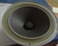
MJL21193 said:I followed Bud's directive for applying the pattern. I used PVA wood glue and a pencil to do it - I guess this invalidates the results.
Not the recommended materials but that shouldn't invalidate the experiment. I would add the gloss.
Those are the 8" stamped basket Corals out of a set of RS MM1000 (?)? Have you ever run across a set of the accompanying tweeters with the foam surrounds intact?
dave
- Status
- Not open for further replies.
- Home
- Loudspeakers
- Multi-Way
- EnABL Processes