swak,
Absolutely, use the Mamboni process first. That 1.5 kZ peak is almost certainly a systemic resonance, likely related to the length of the cone from inner circumference to outer. The Mamboni process will help with this to a degree, as it will dissipate this energy and largely remove the edge terminus that is the probable cause here. I would use the PVA for the entire back side of the cone and then use it for the felt also. This will enhance the boundary layer on the cone backside and also enhance the effect of the felt in terminating that boundary layer properly. Expect to hear a big improvement with doing this.
Adding the EnABL process to the front will also help, as it will raise the amplitude of the surrounding frequencies somewhat and will smooth the following phase cancellations, as you go past the 1.5kZ peak. Very likely the driver will respond to a simple notch filter, after treatment, where before, the single notch would not address the roughness. You can expect to use a fair amount of Micro Gloss on these big cones so buy a few bottles.
I think you will be alarmed by how well this speaker performs when you are done.
Bud
Bud,
thanks for your help, that is great news for me. As for the PVA, is there a particular one that I should look for. I am a little concerned about applying PVA to the whole back of the cone, its a non-reversible process and the drivers are not particularly cheap... but I am very tempted to follow your suggestion. The chassis would probably wont allow for a very consistent cover over the whole surface, would that be problematic? Should the PVA be thinned somehow or applied directly with a brush or piece of foam? And, what kind/make?
Thanks for your help.
Sebastian.
swak,
I have asked a friend, who used this material for a number of years on guitar speaker faces, for manufacturer and part number.
I have to report that I have had mental drift on the name, it is really Polyvinyl acetate not acrylic. It is an acrylic paint and is water soluble and when we used it at Nestrorovic Labs we just gooped it on the cone pretty thickly. You should ping Mamboni, or re read his descriptions to get a clearer picture of how to use it with the triangles.
If my friend still has any data I will pass it on, but I am pretty sure there is only one Polyvinyl acetate, though the well known Elmers White Glue has some additive that Mille Nestorovic felt made it less useful for speakers. Something about surface hardness with the Elmers product that he did not like.
Here are some comments on the material and it's additives.
A vinyl resin, one of the clear, water-white, thermoplastic synthetic resins produced from its monomer by emulsion polymerization. Polyvinyl acetate, abbreviated PVA , has the advantage over the other resinous adhesives in that it is available in the form of an emulsion that is readily diluted with water, is easily applied, and is safe to use because it contains no flammable solvents. In addition, there is no need to use preservatives or fungicides because it does not deteriorate quickly and is unaffected by mold or fungi. The emulsion does slowly hydrolyze, however, and should not be stored for more than one or two years before use. Freezing also destroys the emulsion; therefore, precautions must be taken to avoid exposing it to temperatures near or below the freezing point
The synthesis and patenting of vinyl acetate monomer by Dr Fritz Klatte in 1913, in Germany, provided the foundation for many valuable and now essential plastic products. He found that the catalysed reaction of acetylene with acetic acid gave a readily polymerised low boiling liquid (vinyl acetate) to yield a potential range of dense solid materials. These are now often denoted as (PVAc) or (PVA) polymers.
Klatte and others found that PVA was compatible with other polymers and plasticisers which could give valuable adhesives and coatings for cellulose and textile products. From c.1930 many companies manufactured a range of products such as PVA for liquid solutions and emulsions and hot melt adhesives and paints.
PVA is not an ideal moulding plastic so the development of many economic and attractive alternatives rapidly ensued based on the ability of vinyl acetate to co-polymerise with many other monomers. Hence, co-polymers with vinyl chloride, acrylic monomers, styrene, ethylene and others gave a great range of moulding, coating, sheeting, adhesives, insulating materials, etc.
Hydrolysed versions of PVA gave polyvinyl alcohol as a water-soluble coating and binder. The polyacetal derivatives of these have provided superior bonding and electrical insulation with good stability.
Emulsion paint and adhesive sticks, so readily accepted, are simple examples of these truly outstanding contributions to modern life.
Bud
One of those calligraphy pens with the biggest tip they had. (Also suprisingly cheap to buy)What did you use as an applicator?
Nope...did not know that was the aim. 31 pairs I got.... it's on a Bastanis Prometheus 12" "midband" supposed to go up to around 8k.Were you able to get 36 sets of blocks?
swak said:As for the PVA, is there a particular one that I should look for. I am a little concerned about applying PVA to the whole back of the cone, its a non-reversible process and the drivers are not particularly cheap... but I am very tempted to follow your suggestion. The chassis would probably wont allow for a very consistent cover over the whole surface, would that be problematic? Should the PVA be thinned somehow or applied directly with a brush or piece of foam? And, what kind/make?
http://www.t-linespeakers.org/design/tweeks.html
I have used this stuff for nigh on 30 years now... as well as the benefits Bud described, it also makes the cone more opaque to sound coming back thru the cone.
I thin it and apply multiple thin coats with a brush. Thinned you need to be fairly quick with it as it will start setting up before you are done.
You might want to practise a bit on a piece of cardboard... i have no problem getting a reasonably consistent coverage -- especially on big drivers where you can easily get the brush under the basket legs. a number of thin coats also helps with this.
dave
Bas,
31 will work just fine. Will even roll off the highs slightly at about 8k Hz.
When you go back to the store with the A series pen tips for calligraphy, ask if they have Polar Coordinate Graph paper. Use of this and a set of mechanical dividers (compass with two needles) will allow you to make a pattern for any size driver, without having to resize one of my uploads in photo shop. You will find it's use very intuitive and helpful.
After determining an outer perimeter size with the dividers, you can make a couple of rows in pencil, just one or two blocks and choose a row one or two spaces smaller than the inner block row, make a full single row set and cut the paper to size to use for a template. This means that your pattern row should be about 4 rows, maybe 5 rows, in from the outer perimeter measurement. You will quickly be able to eyeball what you need to do.
This will be one of my early pictures for the Lowther processing which I will begin to post today.
Bud
Hi all,
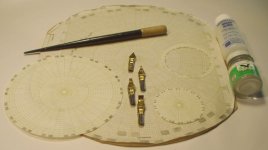
Here is the promised Lowther beginning. The posted picture is of polar coordinate graph paper, applied to my purposes, the pens, Poly S paint and Micro Gloss coating materials. You can see a plan for a 12" driver, a Lowther size driver, a dome (with the blocks on the inside of the ring) and another small block ring. This is all you need, plus some scissors and a decent camel hair brush, to EnABL drivers of any size and configuration.
Bu
Attachments
The link later on in this post should take you to a photo album that shows the pieces generated by computer fawning, that you do not really need to use, to EnABL a driver. Mostly I hope they give you some hints on how to use a guide and what it's placement, with regards to the actual painted blocks, should be.
The conic sections show where the actual blocks should be and the flat patterns show where the guides should be and the two together show how much above a flat guide to place the pattern blocks. All together, there will be nine EnAbl block rings.
The whizzer will have three rings at the top of the whizzer, two rings on the cone and one ring over the fold and out onto the ledge that Lowther thinks is a good idea. This means that you should pattern the Whizzer top first so that you can align the shelf pattern, as an offset to the top row of blocks, on the whizzer cone.
Alignment of the bottom two rows on the whizzer would be a nice touch and if I manage to do it, great. It will look better than not, but there will be zero sonic benefits or detriment. Alignment of the top cone and whizzer rows might actually be important sonically so I will enforce that.
Here is the link to the pics. Please resist editing the comments for the pics... I know it will be hard, but I will just become dispirited with my web ignorance and inability to lock my own intelligent comments in place for posterity.
http://picasaweb.google.com/hpurvin...photo?authkey=VnmOeDveOOk#5059385522118969202
Bud
Hi All,
Here are the, probably not very awaited, pdf files to allow you to print out the computer generated package for the Lowther DX4. Set your Acrobat for no page scaling and no auto rotate and centering.
One conic section has been added. It is to be used on the backside of the Whizzer, taped snuggly together, to provide a pen target guide to allow modestly correct patterns on the inside rows, on the main cone. It is called whizzer outside and is not to be used as anything but a pattern ring guide for that difficult to even see smallest ring set on the main cone. All puns and loosely moral interpretations are intended.
Have fun,
Bud
Attachments
Well, ultrakaz has done it again. Look closely at the center domes on the attached Yamaha speaker system. That is the mysterious center dome pattern, with center spot and droplet of PVA on top of the center spot, I have mentioned a few times in this thread.
Bas, John and all who are contemplating treating large cones with center domes, you want to copy this pattern at the joint of the cone and dome. Though, you can squeeze them down into three rows, with the center row of blocks right in the joint, for less of this tedious activity.
The center dome treatment is important also, very important, as it controls the spike of energy from the center dome and controls the evenness of the high frequency dispersion pattern. Note how few blocks are involved, this is the number that you need, between four and ten pairs in two rings, total. Bas, you will be able to remove the round felt pieces you have attached to your cone. This, added to what you have already done, will control the whole cone. Then add Mamboni to the back just for the sake of bliss.
Then look around, our friend Mamboni is also showing up around the edges of the cabinet. You guys are ging to have to hurry to catch up here......
Bud
Attachments

Bud,
Thank you for the pictures you have posted and the Lowther profiles. Do you know if ultrakaz has done before/after measurements of his speakers?
I am uncertain about thinning the PVA glue, it seems you use it pure while planet10 thins it and applies several layers. Planet10: in what proportion are you thinning the glue?
The only place that could be problematic from behind is the around the circumference where the cone is attached to the spider. I suppose there should be no glue on the spider, so it might be a little tricky placing the brush with glue up there without touching the spider.
Sebastian
This next series is in response to a posting by bobhayes in his "Help me kill a fostex artifact" thread in the FULL RANGE gallery. Excellent questions!
You may think in anyway that you wish to, we all do so. Please have another look at the paper posted on the Positive Feedback site.
http://www.positive-feedback.com/Issue21/standingwaves.htm
Scroll to the last graph, right at the end of the paper. Look carefully at the graph and notice that the untreated cone shows evidence of energy that is still radiating from the cone surface. It is still radiating in discreet peaks and troughs, within the time period that our correlator uses for placement of and distance from threat analysis.
Then notice that the untreated cone has ceased to have energy in the same format. There are still some peaks of emitting energy but most has dropped below the test sheets limit. You may think that all of the activity is still going on and I deliberately cut off the chart scale, to prevent you from seeing it. If you were to run this test on your own, you might prove to yourself that I am indeed attempting to hood wink you.
In actuality, the processed cone has just gotten more energy into the air, in a shorter period of time, than the untreated cone was able to. You can see evidence of this in the graphs. Look at the comparison of the first curve sets. Notice that in some discreet frequency points, the treated cone is 9 dB more efficient than the untreated cone. No question in my mind that the conformal coating, used as a boundary layer enhancement is effecting this event.
Now look at the middle graph from the Positive Feedback site. The two cones are emitting energy at about the same rate, at the same point in time. Different frequency points in this decaying energy plot show differences in storage between the two, for differing frequencies, but the amount of power being emitted is within an equivalent level. If the coating was the only effector here, then this graph should also show a noticeable difference in level, everywhere across the frequency band, because a more efficient emitter surface should work more efficiently, regardless of energy levels being worked with.
Something else must be at play here. This is the same tweeter in both sets of tests. The same test set up, same microphone, same computer etc. etc. One day later though. All that seems left is that the pattern is enforcing an increase in energy transfer into the air during this middle graph period and having done so, ceases to allow energy to return in the boundary layer and provide the same “ringing” emission that the untreated cone is producing. There are no other differences between the two test points. So, more efficient emission into the air from a combination of pattern and boundary layer enhancement is the answer, for the paper cone tweeter.
Change the diaphragm materials to poly carbonate, aluminum, titanium and suddenly things are quite different. Same pattern performs the same function, but the conformal coating is reduced to just the area where the pattern blocks are applied or not used at all. Here is where the effectiveness of the pattern shows up. Certainly this pattern increases the boundary layer impedance. Just as certainly, the materials with less boundary layer and higher internal longitudinal wave speed do not require the conformal coating, but do respond to the pattern with the same “character” as found in a drivers where the conformal coating is required.
Bud
I have never tried it or even heard about it before, but I'm just not convinced from the information given that the EnABL process (just the blocks), is actually having any audible effect on the driver. I'm sure it will have a minor effect, just not audible. Bear in mind I am not a scientist of any fashion, so maybe my pea brain just can't handle the data, but I don't understand the following:
quote:
"An effective solution to the problem of transient standing waves on transducers is to apply a low mass pattern of diffraction blocks to the skin effect surface.
quote:
This pattern must allow relatively free passage to a transverse wave in any direction. When placed near a terminus the EnABL pattern eliminates reflections from the terminus back through the pattern, due to the skin effect energy density within the pattern openings."
I just think that if the returning reflection is of such low amplitude to be arrested by these blocks, it wouldn't really be a problem in the first place. Why does the high compliance surround not absorb the wave? At what frequencies is the pattern supposed to be effective?
You may think in anyway that you wish to, we all do so. Please have another look at the paper posted on the Positive Feedback site.
http://www.positive-feedback.com/Issue21/standingwaves.htm
Scroll to the last graph, right at the end of the paper. Look carefully at the graph and notice that the untreated cone shows evidence of energy that is still radiating from the cone surface. It is still radiating in discreet peaks and troughs, within the time period that our correlator uses for placement of and distance from threat analysis.
Then notice that the untreated cone has ceased to have energy in the same format. There are still some peaks of emitting energy but most has dropped below the test sheets limit. You may think that all of the activity is still going on and I deliberately cut off the chart scale, to prevent you from seeing it. If you were to run this test on your own, you might prove to yourself that I am indeed attempting to hood wink you.
In actuality, the processed cone has just gotten more energy into the air, in a shorter period of time, than the untreated cone was able to. You can see evidence of this in the graphs. Look at the comparison of the first curve sets. Notice that in some discreet frequency points, the treated cone is 9 dB more efficient than the untreated cone. No question in my mind that the conformal coating, used as a boundary layer enhancement is effecting this event.
Now look at the middle graph from the Positive Feedback site. The two cones are emitting energy at about the same rate, at the same point in time. Different frequency points in this decaying energy plot show differences in storage between the two, for differing frequencies, but the amount of power being emitted is within an equivalent level. If the coating was the only effector here, then this graph should also show a noticeable difference in level, everywhere across the frequency band, because a more efficient emitter surface should work more efficiently, regardless of energy levels being worked with.
Something else must be at play here. This is the same tweeter in both sets of tests. The same test set up, same microphone, same computer etc. etc. One day later though. All that seems left is that the pattern is enforcing an increase in energy transfer into the air during this middle graph period and having done so, ceases to allow energy to return in the boundary layer and provide the same “ringing” emission that the untreated cone is producing. There are no other differences between the two test points. So, more efficient emission into the air from a combination of pattern and boundary layer enhancement is the answer, for the paper cone tweeter.
Change the diaphragm materials to poly carbonate, aluminum, titanium and suddenly things are quite different. Same pattern performs the same function, but the conformal coating is reduced to just the area where the pattern blocks are applied or not used at all. Here is where the effectiveness of the pattern shows up. Certainly this pattern increases the boundary layer impedance. Just as certainly, the materials with less boundary layer and higher internal longitudinal wave speed do not require the conformal coating, but do respond to the pattern with the same “character” as found in a drivers where the conformal coating is required.
Bud
Bob,
Here is the second 1000 words or so.
The ridged ring cones are a means of mechanically “decoupling” the cone across it’s surface, so that each effective ring encompassed area acts as a piston within the portion of the frequency band that it’s physical construction allows it to. This is a moderately effective means for widening the “piston point” for a cone driver. It does not address standing wave phenomena and applying the pattern and conformal coating to these paper cone types provides the same benefits that are provided to smooth cones, except the smooth cones sound better, due to less surface diffraction artifacts being emitted into the longitudinal pressure waves.
The radial modes require unimpeded access to the terminus edge before they can form and sweep around an emitter surface. If the terminus is effectively removed they have lost one of the necessary components for their formation as an energy storage mechanism. The blocks are formed from thin acrylic paint and applied with a flow controlled calligraphic pen. Very low mass is added to any portion of the driver but the boundary layer.
The speed of sound through any medium is governed by many, often conflicting factors. You can have paper, with a speed slower than air for given frequencies, as is clearly shown in Corrington’s test results. That same cone, in higher frequencies exhibited a speed of sound , longitudinally through the material, much faster than that through air. The conformal coat, working primarily as a boundary layer additive, will tend to even out these differences in paper cones, with reference to the energy that is traveling primarily in the boundary layer, as it emits into that third vector, the adjacent air. This energy that a cone emits, only emits through the boundary layer, there is no alternative. The design of the cone emitter plate is optimized for this transference of energy, over a period of time. The conformal coat, due to it’s elasticity and speed of transverse waves. averages this frequency dependent speed into and through the boundary layer it is now the major constituent of.
The pattern at the end of the boundary layer does just what any change of impedance will do in a boundary layer and causes the energy traveling through and emitting from it, to stack up, out of the boundary layer surface. This means it stacks up into the air and due to the conservation of energy in our physical realm, it does so in a phase and time coherent fashion, if at all possible. This does indicate that the real determinate of “speed” of the emitter wave, across the surface of the cone, in the boundary layer, is going to be controlled by the “speed” of the longitudinal wave being formed in the adjacent air, as it moves across the cone surface, while it accepts this energy, across a period in time. That a material has the ability to have energy bound into a “sound” traveling through its body at speeds greater than the speed of sound through air, doesn’t mean that this material is going to emit, into the adjacent air “sound” that is traveling faster than the speed of sound through air.
It means that the energy, in a confined material will just ring back and forth until all of it has been emitted. The physical thickness of the material in this case, is what controls the length of time it rings. When metal is used in drivers, it is extremely thin and the amount of time it takes to emit the initial wave and subsequent waves caused by this “time to emit” factor is very close to that of an equivalent paper cone, or we would not be able to make sense of the information that is carried by the emitted waves. The pattern in these cases of high transfer speed is all of the impedance needed to effect the same energy transfer characteristics found on the surface of a paper cone with conformal coating applied. The very same sonic benefits occur, but without a conformal coating being added.
Bud
Here is the second 1000 words or so.
I have seen many cones with a ridged surface, or with one or two raised concentric rings. Do these work on the same principle?
The ridged ring cones are a means of mechanically “decoupling” the cone across it’s surface, so that each effective ring encompassed area acts as a piston within the portion of the frequency band that it’s physical construction allows it to. This is a moderately effective means for widening the “piston point” for a cone driver. It does not address standing wave phenomena and applying the pattern and conformal coating to these paper cone types provides the same benefits that are provided to smooth cones, except the smooth cones sound better, due to less surface diffraction artifacts being emitted into the longitudinal pressure waves.
Also, wouldn't this process have more effect on radial modes, if the blocks were glued in a pattern from centre to edge? There is no terminus or surround to prevent radial modes propagating
The radial modes require unimpeded access to the terminus edge before they can form and sweep around an emitter surface. If the terminus is effectively removed they have lost one of the necessary components for their formation as an energy storage mechanism. The blocks are formed from thin acrylic paint and applied with a flow controlled calligraphic pen. Very low mass is added to any portion of the driver but the boundary layer.
quote:
The thin coating increases energy density in the boundary layer of the membrane and a properly formulated coating will allow the transverse energy, in skin effect, to exceed the speed of sound through air.
I thought that the speed of sound in paper, or any material denser than air, was greater than that in air. I would have imagined that this coating, having more density would counter the effect of the blocks, increasing cone internal damping, which I would have thought would add considerable MMS, changing lots of other driver parameters.
The speed of sound through any medium is governed by many, often conflicting factors. You can have paper, with a speed slower than air for given frequencies, as is clearly shown in Corrington’s test results. That same cone, in higher frequencies exhibited a speed of sound , longitudinally through the material, much faster than that through air. The conformal coat, working primarily as a boundary layer additive, will tend to even out these differences in paper cones, with reference to the energy that is traveling primarily in the boundary layer, as it emits into that third vector, the adjacent air. This energy that a cone emits, only emits through the boundary layer, there is no alternative. The design of the cone emitter plate is optimized for this transference of energy, over a period of time. The conformal coat, due to it’s elasticity and speed of transverse waves. averages this frequency dependent speed into and through the boundary layer it is now the major constituent of.
The pattern at the end of the boundary layer does just what any change of impedance will do in a boundary layer and causes the energy traveling through and emitting from it, to stack up, out of the boundary layer surface. This means it stacks up into the air and due to the conservation of energy in our physical realm, it does so in a phase and time coherent fashion, if at all possible. This does indicate that the real determinate of “speed” of the emitter wave, across the surface of the cone, in the boundary layer, is going to be controlled by the “speed” of the longitudinal wave being formed in the adjacent air, as it moves across the cone surface, while it accepts this energy, across a period in time. That a material has the ability to have energy bound into a “sound” traveling through its body at speeds greater than the speed of sound through air, doesn’t mean that this material is going to emit, into the adjacent air “sound” that is traveling faster than the speed of sound through air.
It means that the energy, in a confined material will just ring back and forth until all of it has been emitted. The physical thickness of the material in this case, is what controls the length of time it rings. When metal is used in drivers, it is extremely thin and the amount of time it takes to emit the initial wave and subsequent waves caused by this “time to emit” factor is very close to that of an equivalent paper cone, or we would not be able to make sense of the information that is carried by the emitted waves. The pattern in these cases of high transfer speed is all of the impedance needed to effect the same energy transfer characteristics found on the surface of a paper cone with conformal coating applied. The very same sonic benefits occur, but without a conformal coating being added.
Bud
Bob wrote,
I do. In my personal system I have a filled poly cone woofer mated to a cloth dome midrange. The cross over is at 800 Hz. The poly cone has a .010 thick coat of conformal material on it, so that it has the same sort of emission of sound characteristics as the cloth dome, with one coat of conformal material. My tweeters are polycarbonate leaf and piezo film and both have a row of dots only at the “bound” edges and a single 50% watered coat of conformal material just over the tiny pattern blocks, for complete control of the emitter surfaces.
The entire process allows significant control over this “mush” caused by phase dislocations. The typical “blending” distance for a treated driver is measured in single digit inches, rather than multiple feet with the untreated version of the same driver, if we are talking under 800 cycles as a nominal reference value for frequencies. In general, above this point the “blend” point is not observable as a distance off the driver surface, in a treated driver, while the untreated driver may take several inches.
It is all of those. Our threat assessment correlator, that we call hearing, uses wide band, low amplitude transient information, to construct an actionable model of the volume of open air of interest. A lack of coherence in this small amplitude information limits the ability to make threat predictions accurately. In a double blind test run by a man in New York, using treated and untreated single drivers in a stereo pair blind ed individuals said they felt confident enough of the cues they were receiving about the playback through the treated speakers to enable them to move within the space the speakers were defining So, phase and time related reflections were recreated with enough fidelity for them to recognize the size and placement of objects in the volume that the recording was made in. Just shows you how good the information that all of the pro engineers have been recording actually is, when the speakers get out of the way.
Not greatly so. The conformal coating is an industrial floor wax and so must be reasonably flexible in the longitudinal plane while being less so in a transverse plane, just to perform it’s designed function as floor wax.
If the major energy coupling were to the whole mass of the cone, yes this would be true
No, it is moving at the optimum speed for energy transform, from transverse wave to longitudinal wave, through the boundary layer.
That is a correct assumption for a two vector energy transmission. When the third vector is added, this energy transform modifies the transverse wave speed at the boundary layer, which is emitting into the adjacent air, not traveling down the boundary layer as a transverse wave. When a material that controls the transverse to longitudinal wave is uniform and has an end impedance that is soft enough to act as an infinite, unterminated surface, but still an impedance, then conservation of energy will be the ultimate control. If that conformal coating, or the raw boundary layer by itself, is capable of a transverse wave speed across its surface, faster than the speed of sound through air, the combination of soft impedance terminus and conservation of energy will maintain the transverse wave of exiting energy into longitudinal wave at the speed of the longitudinal wave as it is crossing the boundary layer controlled surface.
Bud
Why not use a driver made from a different material such as PVC, GRP or CRP instead?
I do. In my personal system I have a filled poly cone woofer mated to a cloth dome midrange. The cross over is at 800 Hz. The poly cone has a .010 thick coat of conformal material on it, so that it has the same sort of emission of sound characteristics as the cloth dome, with one coat of conformal material. My tweeters are polycarbonate leaf and piezo film and both have a row of dots only at the “bound” edges and a single 50% watered coat of conformal material just over the tiny pattern blocks, for complete control of the emitter surfaces.
quote:
Coating the membrane overcomes phase transfer dislocations, found on all boundary layers, by allowing a more uniform energy transfer per given area of radiation.
I would have thought any phase transfer dislocations would be inaudible or immeasurable at anything over a few inches from the driver, where the wave becomes spherical in the bass and lower mids, and directional thereafter due to the complete mush of interacting waves off axis. Would the coating not simply alter these dislocations, rather than 'overcome' them? Surely the coated driver cannot be immune to the phenomena.
The entire process allows significant control over this “mush” caused by phase dislocations. The typical “blending” distance for a treated driver is measured in single digit inches, rather than multiple feet with the untreated version of the same driver, if we are talking under 800 cycles as a nominal reference value for frequencies. In general, above this point the “blend” point is not observable as a distance off the driver surface, in a treated driver, while the untreated driver may take several inches.
quote:
This interleaving of fricative sound interferes with time signature recognition and a reduction in depth of field information is the result.
What is depth of field information? Is it resolution or dynamic range or something else?
It is all of those. Our threat assessment correlator, that we call hearing, uses wide band, low amplitude transient information, to construct an actionable model of the volume of open air of interest. A lack of coherence in this small amplitude information limits the ability to make threat predictions accurately. In a double blind test run by a man in New York, using treated and untreated single drivers in a stereo pair blind ed individuals said they felt confident enough of the cues they were receiving about the playback through the treated speakers to enable them to move within the space the speakers were defining So, phase and time related reflections were recreated with enough fidelity for them to recognize the size and placement of objects in the volume that the recording was made in. Just shows you how good the information that all of the pro engineers have been recording actually is, when the speakers get out of the way.
quote:
The difference in output comes from greater effective emitting area and less resistance to impulse acceleration in the boundary layer.
So the cone is stiffer?
Not greatly so. The conformal coating is an industrial floor wax and so must be reasonably flexible in the longitudinal plane while being less so in a transverse plane, just to perform it’s designed function as floor wax.
That would make the drivers HF rolloff earlier wouldn't it? (Voice coil coupled to less flexible cone would imply the VC impedance rising at a lower frequency than that of the original cone driver, due to seing more mass, more quickly.)
If the major energy coupling were to the whole mass of the cone, yes this would be true
So the traversing wave is moving faster?
No, it is moving at the optimum speed for energy transform, from transverse wave to longitudinal wave, through the boundary layer.
How does this benefit the driver? Since the wavefront propagating from the cone nearest the voice coil moves through the air very slowly compared to the wave in the cone, the emitted wave front will be initially concave (assuming a normally mounted driver) at all frequencies that the cone is capable of reproducing (due to size limitations), regardless of what the cone is composed of (within reason) IMO.
That is a correct assumption for a two vector energy transmission. When the third vector is added, this energy transform modifies the transverse wave speed at the boundary layer, which is emitting into the adjacent air, not traveling down the boundary layer as a transverse wave. When a material that controls the transverse to longitudinal wave is uniform and has an end impedance that is soft enough to act as an infinite, unterminated surface, but still an impedance, then conservation of energy will be the ultimate control. If that conformal coating, or the raw boundary layer by itself, is capable of a transverse wave speed across its surface, faster than the speed of sound through air, the combination of soft impedance terminus and conservation of energy will maintain the transverse wave of exiting energy into longitudinal wave at the speed of the longitudinal wave as it is crossing the boundary layer controlled surface.
Bud
Bob's final questions,
This was a CSD test and did actually produce a full waterfall. At the time I did not think the full waterfall was a need and so the engineer running the test chose what he thought were the important points to note. I don’t know what the gates are either and I do not know anything about the signals used and then Fourier transformed into frequency vs time vs amplitude plots.
I have no idea what you are speaking of here. The time domains chosen were, I was told, the full power response point, the time point after impulse that corresponded to the energy that had reached the outer terminus of the cone, just after the first cycle, so it included voice coil ringing. The last was from when the voice coil was expended and all of the remaining emission was from standing wave ringing from the cone only. I have no experience in this sort of testing and can only rely upon the information given to me.
In certain sorts of emitters the conformal coating is what allows the pattern to control the standing waves, that will ring on an uncontrolled surface, and still produce intelligible and attractive information. In other situations it is detrimental to that same process.
I strongly suggest you duplicate the cones used by Corrington and pointed to in Beranek’s book “Acoustics” in the seventh chapter, Part XVIII, beginning on page 195. Special attention is due section 7.11 “Diaphragm Behavior” on page 199 and on through page 207. These are simple paper cone drivers with a corrugated paper surround. These are still made and used in sound reinforcement / music distribution systems in commercial buildings throughout the civilized world. These will provide you with the fewest possible distracting elements.
I absolutely agree. I don’t claim better. I claim less, “noise”.
A very problematical downside is the performance attributes of the upstream components that are revealed. Not always to the enjoyment of the listener.
Equal regard,
Bud
quote:
These claims are demonstrable and measurable. The enclosed frequency response plots are from FFT processing of an .006ms duration square wave pulse test, with gates set at 0.00 and 5.5ms.
I make that a 57.333kHz square wave. My hearing is duff over 16kHz.
I don't know what the gates are, but they are set at (high) infinity Hz and (low) 62.5kHz?
There are no labels on the y graph axis, is it SPL dB?
This was a CSD test and did actually produce a full waterfall. At the time I did not think the full waterfall was a need and so the engineer running the test chose what he thought were the important points to note. I don’t know what the gates are either and I do not know anything about the signals used and then Fourier transformed into frequency vs time vs amplitude plots.
There is no doubt the graphs show changes to the driver, but I cannot see the relevance of 0.19mS (1.8MHz), 0.35mS (983kHz) and 1.19mS (289kHz) in audio transducers. (unless they were hypersensitive to RF instability or something.)
I have no idea what you are speaking of here. The time domains chosen were, I was told, the full power response point, the time point after impulse that corresponded to the energy that had reached the outer terminus of the cone, just after the first cycle, so it included voice coil ringing. The last was from when the voice coil was expended and all of the remaining emission was from standing wave ringing from the cone only. I have no experience in this sort of testing and can only rely upon the information given to me.
Sorry if I got it all wrong, but it seems to be 'talking up' the actual problem, and I'm not sure the EnABL process (the blocks part) described is effectively combatting any audible driver cone anomalies. I think the coating is the major contributer to any measuable or audible changes.
In certain sorts of emitters the conformal coating is what allows the pattern to control the standing waves, that will ring on an uncontrolled surface, and still produce intelligible and attractive information. In other situations it is detrimental to that same process.
I'm hoping to get a cheap test setup together soon, to measure changes in response for different mods to generic drivers, but I have no ability to test and interpret such complex cone resonance issues, so I'll still be non the wiser.
I strongly suggest you duplicate the cones used by Corrington and pointed to in Beranek’s book “Acoustics” in the seventh chapter, Part XVIII, beginning on page 195. Special attention is due section 7.11 “Diaphragm Behavior” on page 199 and on through page 207. These are simple paper cone drivers with a corrugated paper surround. These are still made and used in sound reinforcement / music distribution systems in commercial buildings throughout the civilized world. These will provide you with the fewest possible distracting elements.
That said, I will try these mods out and compare, because after all, it's not a test setup, computer or microphone that will be listening to the drivers, and there is no better judge than the ol' ears.
For any change made to the characteristic of a transducer, it is purely subjective as to whether it sounds 'better', as there has never been, and never will be a 'perfect' one (even if there was, everyone would argue it was 'too' perfect). For all the technical advantages in using modern materials and processes, some people would still not trade their paper drivers for anything else. This in itself speaks volumes. Everyone here knows all about compromise, and for every positive action, their will always be a trade off.
I absolutely agree. I don’t claim better. I claim less, “noise”.
A very problematical downside is the performance attributes of the upstream components that are revealed. Not always to the enjoyment of the listener.
If there is discussion of this topic elsewhere, please let me know, so maybe I will get a better grip on what is happening as I still don't fully understand.
Regards, Bob.
Equal regard,
Bud
I'm not a fast reader, and have not finished reading the prevous posts, but I think that a few things we should take note of.
1. The article in Positive Beedback talks of a 1.75" paper tweeter, and since both the pattern and cone coating is used, we see a difference which cannot distinguish between just the coating alone, versus coating plus pattern. Depending on the type of surround used on the driver, the additional coating alone could have made the mechanical impedance difference between the cone and the surround smaller so that energy is dissipated into the surround.
2. The 1.75" paper tweeter driver can be effected by a mass as low as 0.2 grams, and we do not know how much weight the pattern is.
3. Normally pattern size should have some relation with the most significant wavelength it's supposed to deal with. This is something worth investigating.
4. No measurable differences have been shown in larger drivers. Since Bud is working on some drivers right now, it would be nice to see some "response before" and "response after".
5. I think one thing I am going to do is investigate some of my data and see if this reflection characteristic can be found. Reading the article Bud posted on the Positive Feedback site lead me to think about distinguishing cone breakup versus reflection.
6. I wouldn't expect this to be a solution for cone breakup unless the mass of the pattern is significant enough to change those modes.
One driver that comes to mind that might worth a try is the Jordan JX92S. This driver is known to be a little rought at the high frequencies, smoothing that out really will make it stand out.
swak,
You might ping planet 10 on PM. He is a busy man but always seems to find time to answer questions he knows about.
Personally I would copy his many thin layer approach. What was done at N Labs was a production process, we already knew we wanted a bunch of the PVA on the cone. The surround, spider and motor were all built to handle that extra mass.
The backside coating is going to require care. Application of a small amount of PVA on the inner spider will not hurt. We actually did this on the larger (15 inch) woofers that we basically doubled the mass of so that the spider would not crack at this joint. The epoxy that is used to attach the spider to the voice coil will wick into the spider and this causes work hardening and eventual fiber breakage when large excursions are common. Adding a small amount of stiffness here may also help keep the voice coil from moving out of the gap, due to the increased mass of the PVA, so, you might just do the inevitable, deliberately.
You are welcome to the pictures. Please do not hesitate to ask for details of what I do, as I proceed through the Lowther treatment. If we can get the process steps down and provide a reliable improvement in performance, it will benefit a lot of folks who have spent a lot of money on these machines.
Bud
soongsc,
I agree, in fact I am certain that the mechanical impedance is altered, just not certain in what combination of directions. With so small a cone and with it's elasticity so great, the addition of the coating , since it does permeate a paper that thin, has to be profound. Doesn't mean profoundly bad either.
My assumption, after many hundreds of cones treated in this fashion, is that the properties of the conformal coating are generally beneficial. This is true only if the coating is used with circumspection and with some thought given to exactly the question you raise here. That the coating needs the pattern at start and finish of the cone is just as obvious from these many examples.
Something that needs to by quantified. We are connected by a world wide postal service, until the fuel runs out. If you have the expertise and equipment to look into this and many other aspects, I will certainly participate.
This has always been a troublesome question. I think the answer is a qualified "yes that is true". The qualification being that in a situation where the blocks are quite large, as they are when used to control the edge refraction on a speaker cabinet, in comparison to what might be found on the outer circumference of a cone driver mounted on that front panel that is patterned with those large blocks, the frequencies all act with coherence and all seem to be effected in the same manner by these large blocks. Affected in a manner similar to that of the smaller periphery blocks provided, at the cone terminus, while emitting these frequencies.
So, I am not convinced that there is more than a loose relationship. Or, the treated cone is emitting so coherent and self supporting a wave that the additional blocks at the panel edge just act as a subsidiary control. to maintain that coherence. This is supported to a degree. by the one wave tank test I performed many years ago, where the emitted waves flowed to the end of the tank and dispersed with no observable reflections. There are wave structures like this in nature, they are called Soliton Waves.
I have been quite frustrated in my limited teat suite and knowledge of procedures. I do not have a MLSSA or other CSD capable test device. With my main revenue stream, transformers, mired in such a dismal business climate, I will not be able to remedy this lack on my own. I can supply samples, processed to differing levels of completion, but not a lot more than that and many years of experimentation.
My experience has been, that with both parts applied, cone breakup is somewhere out beyond the stable power handling ability of the voice coil. I have had test samples catch fire in the motor, with only a mild amount of very linear compression being audible. Very very loud compression, but not the usual garble, leading to complete dissonance, typical of the untreated sample drivers. These tests cannot be entered as anything but anecdotal evidence, since no particular attempt to provide controls was followed. It does seem to be pervasive however.
The only comment I can make is that cone breakup may be more profoundly influenced by standing wave corruption, of following signals, than is generally realized. I think a very close look into this will be, at least, educational. Regardless of the eventual findings, I do think this is an entangled event and not a clearly understood entanglement either.
Be happy to provide my abilities. However, i do think that objective tests should be on a simple paper cone, as noted in my long response to bobhayes, similar to the one Corrington used in the 50's.
Bud
1. The article in Positive Feedback talks of a 1.75" paper tweeter, and since both the pattern and cone coating is used, we see a difference which cannot distinguish between just the coating alone, versus coating plus pattern. Depending on the type of surround used on the driver, the additional coating alone could have made the mechanical impedance difference between the cone and the surround smaller so that energy is dissipated into the surround.
I agree, in fact I am certain that the mechanical impedance is altered, just not certain in what combination of directions. With so small a cone and with it's elasticity so great, the addition of the coating , since it does permeate a paper that thin, has to be profound. Doesn't mean profoundly bad either.
My assumption, after many hundreds of cones treated in this fashion, is that the properties of the conformal coating are generally beneficial. This is true only if the coating is used with circumspection and with some thought given to exactly the question you raise here. That the coating needs the pattern at start and finish of the cone is just as obvious from these many examples.
2. The 1.75" paper tweeter driver can be effected by a mass as low as 0.2 grams, and we do not know how much weight the pattern is.
Something that needs to by quantified. We are connected by a world wide postal service, until the fuel runs out. If you have the expertise and equipment to look into this and many other aspects, I will certainly participate.
3. Normally pattern size should have some relation with the most significant wavelength it's supposed to deal with. This is something worth investigating.
This has always been a troublesome question. I think the answer is a qualified "yes that is true". The qualification being that in a situation where the blocks are quite large, as they are when used to control the edge refraction on a speaker cabinet, in comparison to what might be found on the outer circumference of a cone driver mounted on that front panel that is patterned with those large blocks, the frequencies all act with coherence and all seem to be effected in the same manner by these large blocks. Affected in a manner similar to that of the smaller periphery blocks provided, at the cone terminus, while emitting these frequencies.
So, I am not convinced that there is more than a loose relationship. Or, the treated cone is emitting so coherent and self supporting a wave that the additional blocks at the panel edge just act as a subsidiary control. to maintain that coherence. This is supported to a degree. by the one wave tank test I performed many years ago, where the emitted waves flowed to the end of the tank and dispersed with no observable reflections. There are wave structures like this in nature, they are called Soliton Waves.
4. No measurable differences have been shown in larger drivers. Since Bud is working on some drivers right now, it would be nice to see some "response before" and "response after".
I have been quite frustrated in my limited teat suite and knowledge of procedures. I do not have a MLSSA or other CSD capable test device. With my main revenue stream, transformers, mired in such a dismal business climate, I will not be able to remedy this lack on my own. I can supply samples, processed to differing levels of completion, but not a lot more than that and many years of experimentation.
5. I think one thing I am going to do is investigate some of my data and see if this reflection characteristic can be found. Reading the article Bud posted on the Positive Feedback site lead me to think about distinguishing cone breakup versus reflection.
My experience has been, that with both parts applied, cone breakup is somewhere out beyond the stable power handling ability of the voice coil. I have had test samples catch fire in the motor, with only a mild amount of very linear compression being audible. Very very loud compression, but not the usual garble, leading to complete dissonance, typical of the untreated sample drivers. These tests cannot be entered as anything but anecdotal evidence, since no particular attempt to provide controls was followed. It does seem to be pervasive however.
6. I wouldn't expect this to be a solution for cone breakup unless the mass of the pattern is significant enough to change those modes.
The only comment I can make is that cone breakup may be more profoundly influenced by standing wave corruption, of following signals, than is generally realized. I think a very close look into this will be, at least, educational. Regardless of the eventual findings, I do think this is an entangled event and not a clearly understood entanglement either.
One driver that comes to mind that might worth a try is the Jordan JX92S. This driver is known to be a little rough at the high frequencies, smoothing that out really will make it stand out.
Be happy to provide my abilities. However, i do think that objective tests should be on a simple paper cone, as noted in my long response to bobhayes, similar to the one Corrington used in the 50's.
Bud
There is a solution for those that can't find polar graph paper.
Graph paper printer
Regards
James
Graph paper printer
The options are available through dropdown pick-lists:
Cartesian, polar, triangular, hexagonal, axonometric and dot diagrams.
Linear scales (metric, imperial, time, equal divisions, customizable).
Non-linear scales (logarithmic, quadratic, gaussian, square root, Weibull, logit).
Music manuscripts and tablatures.
Mercator grids.
Pattern papers (lines, bricks, losanges, ellipses, hexagons).
An externally hosted image should be here but it was not working when we last tested it.
Regards
James
- Status
- Not open for further replies.
- Home
- Loudspeakers
- Multi-Way
- EnABL Processes