Hi Alan,
You are very likely to have been the first under the wire! Thanks for describing the latitude you took with materials and techniques. That you discovered how to uncover sonic clarity with odd dots and unusual techniques will help to encourage others to experiment.
Please do report on the effects of your further explorations into this argumentative exercise.
Bud
Hi Bud.
Thanks for sharing your treatment.
It works for me.
Yesterday I enabled a cheap speaker using your pattern.
Method and brand are not as you recommend, not as regulier as it would be, but, yes... it works.
Instruments are more separated, timbre is more correct and more dynamic.
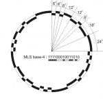
An idea comes to me to use a pattern which have more random characteristic. That pattern is MLS (maximum length sequence).
So, I used base-4 MLS which give me 111100010011010 (1=6degrees painted, 0=6degrees non painted).
Your pattern looks like 1101100000 (1=2degrees painted, 0=2degrees non painted).
To my ear, on that cheap nude speaker, MLS is better than yours.
Especially on violin.
I was really surprised, how a poor nude speaker can sound like that.
Now, I'll try to find my time to treat my Fostex properly.
Again, thank you Bud.
Regards,
Atok
PS: There is another pseudo random sequence known as Baker Codes.
Thanks for sharing your treatment.
It works for me.
Yesterday I enabled a cheap speaker using your pattern.
Method and brand are not as you recommend, not as regulier as it would be, but, yes... it works.
Instruments are more separated, timbre is more correct and more dynamic.
An idea comes to me to use a pattern which have more random characteristic. That pattern is MLS (maximum length sequence).
So, I used base-4 MLS which give me 111100010011010 (1=6degrees painted, 0=6degrees non painted).
Your pattern looks like 1101100000 (1=2degrees painted, 0=2degrees non painted).
To my ear, on that cheap nude speaker, MLS is better than yours.
Especially on violin.
I was really surprised, how a poor nude speaker can sound like that.
Now, I'll try to find my time to treat my Fostex properly.
Again, thank you Bud.
Regards,
Atok
PS: There is another pseudo random sequence known as Baker Codes.
leo van doorn,
I will apply virtual dots for you. They will be the same as those applied to the Hemp FR8 driver I treated a short while ago. You might want to look here to see how that driver is patterned.
http://picasaweb.google.com/hpurvine/HempFR8
These are difficult drivers to tame. They have a couple of phase issues between main cone and whizzer that are aggravated by having a shelf extending from the outer rim of the whizzer cone.
The picture you provided does seem to show a similar ledge or shelf on the Beyma driver. You will need to obtain an acrylic paper cement that remains "sticky" after drying and coat the outside of the whizzer with this material and also the center dome, but none of the interior vertical surfaces, at the voice coil whizzer joint.
There is also the issue of finding the main ringing node location, on both cones, and applying a pattern to disperse them. This is not a requirement for excellent sound, but certainly moved the Hemp driver into the highest levels of musical reproduction I have heard. These intermediate rings are also shown in the Hemp pictures.
Unfortunately I cannot simulate their location on the Beyma without actually having the drivers in my possession. I do not have FEA software and only one instance of having found and dispersed this systemic storage mechanism to date.
It will be a couple of days before I can get to virtual dots for you, due to transformer concerns that allow me to continue to live in doors.
Bud
Atok,
Hmmmm, now that is very interesting. I have a dozen inexpensive 5X7 oval drivers with whizzers I now intend to use to explore just what you are describing, along with some other ideas that have occurred due to being carefully questioned by a number of folks.
Because I am ignorant of the MLS pattern, or randomness, is there a simple and direct derivation, as that fragment you have shown, that will describe how it works out for a circle? Or am I misunderstanding and the sequence you have given is a simple repetition for a sector?
I will try to figure these out, both the MLS and Baker Codes, but any simple format you can point me to would be helpful.
I have always assumed that my scratchings on the surface of this knowledge would be quickly surpassed by folks with better brains and superior tools for analysis, once I convinced enough of those folks to take a hard look at these issues I am raising. I welcome your help and explorations.
Bud
BudP said:Hi CJ,
Due to the EnABL process not allowing drivers to excite typical room node resonances, you will also have very clear and extremely well textured bass from the Dayton driver.
Bud
This is impossible. The room nodes will not be effected! Please explain this! You are saying painting dots on the driver will change room nodes?

Bud, I am not saying the dots don't do something to the sound of the driver but eliminate room nodes?
If you will kindly explain this phenomena I'd be most welcome.
Magnetar,
Please pardon my generalization.
I should have been much more specific and said that the drivers will not excite room nodes that rely upon feed back, with the standing waves created upon all untreated driver surfaces, at all frequencies, as same frequency ringing.
Those nodes within a room, that do not require a feed back relationship with the speaker will ring, regardless of the activities of a driver and baffle that do not have standing waves upon their surfaces.
As for removing diffraction at cabinet edges, I have many working examples. The disappearing act is only with regard to those diffractions that locate an emitter within a volume, as a perceivable source of sound emissions. The boxes do not become invisible with respect to any other perceptual mechanism.
What I have not experimented with is open baffles and do not yet claim mastery there. I am not assuming I will fail to control these diffractions, by eliminating the standing waves mechanisms that are their cause. I can claim, with confidence, that I can eliminate standing waves from a baffle surface, with blocks of paint. I have done so.
Once again I find I should have been more specific. When you have an uncontrolled driver, on an uncontrolled baffle, there will be numerous feedback reinforced standing wave events, due to the physical parameters involved. Once you have controlled the driver surfaces, the remaining feedback induced standing waves, found on the baffle surface are only those that are defined by the baffle edges. Once these are dispersed, the standing waves that drive baffle diffraction are eliminated.
If you know of other diffraction modes please post about them, I am truly ignorant of them. I have no experience of them, in my controlled drivers and baffles. It is quite possible that I am as ignorant of other modes of diffraction, as many people are of the effects of EnABL'd dispersal of those, created by standing waves.
Bud
This thread gets more facinating by the day. BTW, I assume that EnABL is an acronym for something, but as yet have yet to see it spelled out. Bud?
Noe I have to ask a dumb question maybe...
The patterns showed, how do you apply them. Do You print them on papper, cut out the black "square" and use the remaing part as a guide when painting, or?
The patterns showed, how do you apply them. Do You print them on papper, cut out the black "square" and use the remaing part as a guide when painting, or?
TNT,
Look here for a tutorial of the "standard" method of application of these rings of blocks. Read down to page 8 and 9 or just jump directly.
http://www.hawthorneaudio.com/forums/viewtopic.php?f=2&t=1429
There are many different methods that have been explored though. PDAN used clear cellophane tape, others have used post it notes and masking tape, typewriter whiteout, tooth paste and likely others I have forgotten.
konut,
Enhanced Acoustic Boundary Layer
Atok,
Delicious. I will apply it to two of the 5X7 drivers on cone and whizzer.
Thank you.
Bud
Magnetar:
Perhaps the raised dots act as the dimples on a golfball do and affect the laminar flow of the air?
John C.
Perhaps the raised dots act as the dimples on a golfball do and affect the laminar flow of the air?
John C.
BudP said:Hi Alan,
You are very likely to have been the first under the wire! Thanks for describing the latitude you took with materials and techniques. That you discovered how to uncover sonic clarity with odd dots and unusual techniques will help to encourage others to experiment.
Please do report on the effects of your further explorations into this argumentative exercise.
Bud
Will do Bud. The patterns were standard. I figured if the guy who used toothpaste got results, then so would I. There was also some stuff suggesting that slightly sloppy implementation might even work better.
Re the communal grumpiness about cabinet claims. I have a very simplistic view of some energy getting trapped and bouncing about in horizontal planes. And being dispersed when it hits these patterns.
What if you enabl'd your ears!? 😉
LAL,
Sorry for the delay, you got kind of lost in the shuffle. The Gloss coat, full strength, should cover as much of the phase plug as you can get to, without also painting the inside of the voice coil. If you can remove the phase plug, paint the entire length and also put a ring set right at the bottom of the plug, in addition to the two plus tip control you can see in the virtual photo.
Bud
Ok, I'm getting ready tpo do some ENABL patterns - what I'm going to try is some acrylic gesso (high solids content), and I just ordered some Micro Coat satin finish from Micro Scale. Is the Micro Coat applied 1/2 strength?
Also, I have a bunch of the cheapo Pioneer 4" drivers from P.E. that folks were using for line arrays. Has anyone tried the treatment on them? As I recall, they had some high end rattiness that could do with some treatment.
Also, I have a bunch of the cheapo Pioneer 4" drivers from P.E. that folks were using for line arrays. Has anyone tried the treatment on them? As I recall, they had some high end rattiness that could do with some treatment.
wrenchone,
Umm, you might want to contact Micro Scale and change that to Gloss Coat.
The Satin is useful as a foil to the Gloss, for someplace where you have two different speed materials and you want to retard one of them and speed up the other, to match phase. We are talking material that sound travels through at about 3600 fps and the rougher the surface the slower the entire energy transfer event is, by, not big, but definitely audible amounts.
The flat is also useful in this respect. Think of it as having slicked up the surface with Gloss coat and then using the Flat and Satin to slow that slippery surface down. Or think of it as impedance matching. However you need too, that allows you to recognize and use the tools, where you need them.
There is also an acrylic, clear drying, contact cement that, once the other surfaces are slicked up with Gloss, will tend to exclude energy from using a surface to traverse and emit from. Using this on the back side of whizzer cones works very well, to quell the fight between cone top surface and whizzer bottom surface.
You will find that this is a very subtle art. Once you have your correlator tuned into the gobs of information, you will begin to see how to use the various surface tools, to get an EnABL patterned cone to provide an extremely close rendition of the reality, that was the original source, for the recording you are listening to.
This will begin to be apparent and very useful, by perhaps the third or fourth set of drivers you treat, each of them further sensitizing your hearing to what might be possible.
Have fun.
Bud
TNT said:The effect comes from "mass" rather than physical obstruction - or?
Do you mean that what we are hearing is just from the addition of the mass?
I can tell you that my experiments/experience clearly show that this is not the case. My new drivers (FE126eN/FE127eN) have pretty close to the same added mass as my previous drivers and there is no comparison between the before & after. The phenomenom we are hearing is unlike anything i have ever heard adding mass to a driver (and i have been doing that for 30 years)
dave
TNT,
I don't think we know, exactly and it may be that with differing base materials for or locations on the time based emitter, different characteristics are important.
For the most part, it appears that the first ring set, at the voice coil or shortly thereafter, lofts the energy transform from transverse to longitudinal (compression) wave, up out of the laminar zone of the boundary layer. This would show a preference towards obstruction.
This lofting may actually be a stretch of this normally shallow energy transform joint too.
The conformal coating then supplies a guarantee of 3 + times the speed of sound, throughout it's medium.
The final set of rings appears to both loft the, perhaps sinking, transform joint, again as an obstruction, but to also enforce an energy density, within the conformal coating, not obstructed by the pattern, that disallows the energy that is still exiting into the boundary layer, out at this edge, from bouncing off of the edge and re traversing the cone, in the boundary layer, down on the laminar zone, where it would ring as a standing wave and corrupt following energy signals. Here it would seem that local mass, in the boundary layer, is as important as obstruction from the patterns.
What information we have, from the primarily longitudinal based test regimens, seems to support this dual nature. Interestingly, Soongsc, who provided the bulk of this test information, has also discovered that a ring set, applied in a specific location on the emitter surface, can disperse a nodal standing wave, one that arises due to the system of physical factors that comprise the emitter.
These nodes are usually seen in CSD plots, as a frequency response hole, that becomes a strongly emitting "nose" of energy at a specific frequency and exits for far longer than the rest of the driver's surface takes to quit ringing.
I have completed a "study" of a pair of Hemp FR8 full range drivers, that utilize this extra set of rings and they have allowed me to balance emitting surfaces to a level of exactness I would not have believed possible six months ago. The resulting driver is so clear and correct, in it's portrayal of any type of music or sound effects, that I am almost afraid to listen, in case it should all suddenly go pop and sink into some ugly reality.
Sonngsc tests, in a controlled and verifiable test set up, are the reason I finally "gave this away" here in this forum. I was pretty sure someone would see the use and push the envelope wider, just because they come from a different mind set and experience than I do.
Then, the careful and skeptical questioning by folks like Magnetar and MJL21193 has caused a lot of other people to contribute, some in support of and others skeptically, into what has become an exploration into an area of acoustic behavior, where very few people have looked at all.
And now, finally, we are seeing some contributions in patterns that may work even better than the basic EnABL pattern, though I am quite certain that Soongsc has his own pattern set, that he will unleash commercially in due time.
So that is where we are, currently. It was Jon Ver Halen of Lowther America, who voiced the essence of the EnABL surprise, when he asked, after running an exhaustive set of tests, "How can these things measure the same or worse in all of the tests, and yet sound so different from an untreated pair of drivers, while still sounding the same ?" I am paraphrasing Jon, because I don't want to go and dig back through all of those pages to find his exact words either.
Who would have thought this thread would have grown so large, and still just be getting started....yikes!
Bud
For all the folks working this. I just want to mention a concept that the cumulative spectral decay is basically noise from past music effecting the current music. So if we all understand how bad noise is to audio performance, then we know that lowering this noise floor should be first priority for clean and dynamic music. I have actually started to work this route a for a few years trying to get a feel what are the ways to improve sound of existing drivers. This was quite a big task. The second big task is how this can be done on both small scale and in quantities. Hope many ways of delivering clean and dynamic sound come to market to everyone can listen to some good music.
Another member also quite experienced in this area is Mark whom has posted tweaks for TB drivers a while back. I have learned to pay more attention to the impulse data inspired by some of his reports which he has made available to this forum.
There is so much knowledge in this forum, that it really takes a while to bring different ideas together. Working the mechanical to acoustic part is my first priority, because once we get this part improved significantly, all the other tweaks that are controversal will become more evident. Yes, this means the hot issue about cables as well. You will here a very obvious improvement with everything you do right, if a tweak just changes the sound and you cannot decide whether it's better beyond reasonable doubt, then it probably is not better, just different.
Hope everyone has fun.
PS. Once you get the dirvers EnABLed, the next thing to consider is flattening out the impedance curve. Anything not right will be more audible, and needs to be dealt with. Even a 22KHz resonance that I'm trying to tame, which really gets excited when Domingo sings.
- Status
- Not open for further replies.
- Home
- Loudspeakers
- Multi-Way
- EnABL Processes