Note that to "refute" something is to show/demonstrate that it is false, not merely state (or quote from someone else's statement) that it is false (that would be 'dispute', not 'refute').
 That is what happened when Continental Drift was initially proposed. All the socalled experts soon had mud on their face.
TOOOO Bad!!
That is what happened when Continental Drift was initially proposed. All the socalled experts soon had mud on their face.TOOOO Bad!!
An ultralinear mode was a fashion with misleading name. 🙂 Transfer functions by different grids are different, so NFB to the wrong grid does more harm to linearity than no feedback at all. So called "Crazy Drive does an opposite, making the tube indeed more linear.
If you want lower output resistance, go for G1 feedback (so called Schade, or parallel from anode to anode, or secondary to cathode)
If you want lower output resistance, go for G1 feedback (so called Schade, or parallel from anode to anode, or secondary to cathode)


it does make benefit, only if end tubes are high µ🙂I posted this a while ago, so for a yuk I will post it again.
And the changes in internal impedance are quite easily measured.
Cheers to all, John L Stewart
linearizing low µ, bad quality triodes is futile anyways
The jhstewart9 all triode UL amp would make better practical sense with pentode outputs (or high Mu triodes per hpeter) for increased UL loop gain. But the novelty of ALL triodes is certainly appealing for the triode crowd. And avoiding screen current distortion is quite appealing too.
I looked at Moers article and there is one glaring omission in the final comparisons. The pentode case has lots of gain available for a global N feedback loop (or for some local N Fdbk scheme), which is not being used. Use the gain for N Fdbk and it will give the lowest distortion with the highest power output.
I still see UL as just a cheap scheme (no screen supply needed) to get NEAR to Hi-Fi results (screen current distortion is not fixed, leaving all those wigglies in the UL curves). Pentode mode, similarly, doesn't fix the screen current distortion directly either, but can make better use of loop gain for fully linear global/local N Fdbk. Both still suffer from grid 1 transconductance variation versus signal.
Real Hi-Fi deserves better. Classical Pentode mode with global N Fdbk or DHT have done pretty good up until now.
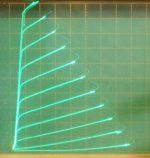
Crazy/Twin Drive with global N Fdbk (and no screen current wigglies OR grid 1 transconductance variation) absolutely blows every historical amplifier right off the planet:
History turned into dust....
.
I looked at Moers article and there is one glaring omission in the final comparisons. The pentode case has lots of gain available for a global N feedback loop (or for some local N Fdbk scheme), which is not being used. Use the gain for N Fdbk and it will give the lowest distortion with the highest power output.
I still see UL as just a cheap scheme (no screen supply needed) to get NEAR to Hi-Fi results (screen current distortion is not fixed, leaving all those wigglies in the UL curves). Pentode mode, similarly, doesn't fix the screen current distortion directly either, but can make better use of loop gain for fully linear global/local N Fdbk. Both still suffer from grid 1 transconductance variation versus signal.
Real Hi-Fi deserves better. Classical Pentode mode with global N Fdbk or DHT have done pretty good up until now.
Crazy/Twin Drive with global N Fdbk (and no screen current wigglies OR grid 1 transconductance variation) absolutely blows every historical amplifier right off the planet:
History turned into dust....
.
Attachments
Last edited:
Thanks for that - a really useful article.
No. Think again.20to20 said:I've thought quite a bit about how UL works and my theory is that it is like a tuning circuit that improves the function of the screen/anode in parallel with the primary coil.
That I can agree with.In the end it is what it is,
Crazy/Twin Drive with global N Fdbk (and no screen current wigglies OR grid 1 transconductance variation) absolutely blows every historical amplifier right off the planet:
History turned into dust....
Sorry to thread-jack but can you cite some example schematics using this scheme ? It looks like what is being considered is driving the screen with some of the signal applied to the grid , which I would assume would apply some feedback , possibly with the addition of plate to grid back to the driver . This particularly interesting to me as I was considering screen drive with plate to grid with some of the smaller sweep tubes . To date I have found the best sounding scheme for pentode SE is to use DC coupling and plate to grid feedback with a DHP . This 'crazy drive' idea to me , sounds like the untrodden path and maybe worth a try 🙂
316a
miracle this schade is, i think a (4cx250) high gm cermet tubes, could be the next tube hobby boom.
The Trioderizer - a solid state triode
The Trioderizer - a solid state triode
[off topic, apologies:]
Mickeystan has built a "Crazy/Twin Drive" 6DQ5 P-P amplifier here:
http://www.diyaudio.com/forums/tube...nificent-television-tubes-67.html#post4675483
There are likely some other amps in progress (several inquiries, SE too), one on the bench here. The front end needs to be able to develop sufficient drive for grid 2, although about 30% less than for pure g2 drive. The TV Sweep type output tubes are most amenable, with their lower grid 2 voltages. Some form of N Fdbk is needed to lower the output impedance.
After some discussion among early investigators, the name is being slowly transitioned to "Twin Drive" from the earlier "Crazy Drive" moniker, to make it more respectable to new designers. "Crazy Drive" might have been more representative of first schematic impressions, from seasoned designers, since it looks unlikely to work. But work it does. Beyond all expectations. Not even any screen kinks left.
Surprisingly, there is no obvious N feedback in the Crazy/Twin Drive scheme. Both grids are driven up front, but one by voltage (grid 2) and the other (grid 1) largely by current. The opposite curvature of each can be adjusted to compensate amazingly well. The no N Fdbk crowd should like that, however, the output Z is like a pentode. So getting the Zout down for damping requires some form of N Fdbk. Local N Fdbk to the driver stage can avoid the need for an expensive high bandwidth OT. (although only limited global N Fdbk is needed for Zout, and that removes the OT winding resistance issue also) Distortion will then be vanishingly low unless one introduces some 2nd or 3rd harmonic in the driver setup. (ie, you don't need classical HIGH level global N Fdbk to get the distortion down, its already low)
..
Last edited:
[off topic, apologies:]Mickeystan has built a "Crazy/Twin Drive" 6DQ5 P-P amplifier here:
Thank you . Very unusual but simple . I drew this in my head with a negative connection for the tail of the potential divider but it appears to be biased positive used 🙂
316a
It all starts back around here: (post 464) (with some clues to how it works in posts 467,468)
http://www.diyaudio.com/forums/tube...nificent-television-tubes-47.html#post4574362
Grid 1 normally starts at 0V (unless there is some small galvanic offset in the internal tube wiring that needs fixing) since it is grid 1 conduction that provides the compensation effects for grid 2's 3/2 power law expansion. Fortunately, very little grid1 current is needed for the effect. Many common TV tubes are trialed in the succeeding posts, with example resistor values shown. If using a pot to select the g2 to g1 resistor for some new tube, be careful to put a limiting fixed resistor (maybe 1000 Ohms) in series to protect grid 1 from excessive current.
------
I'm wondering if there is some practical way to apply jhstewart9's "Triode UL" feedback scheme ( to the HV driver stage), for a local N Fdbk to lower the output Z. Probably easier to just apply N Fdbk to the driver screen grid (crossed for P-P phase).
..
Last edited:
At least to the extent that the ideal % tap is rather variable, the 6V6 gets its own "special" 20% or so tap, I'd have to agree with the tuning idea.. I've thought quite a bit about how UL works and my theory is that it is like a tuning circuit that improves the function of the screen/anode in parallel with the primary coil. .
Threads like this one brings to mind a quote by Samuel Clemens: "It's easier to fool a man than convince him he has been fooled." I can't think of ANY other subject other than tube amps where so many people have such strong opinions about what is best. I learned about 10 years ago to ignore the "noise" make my own comparisons, and reach my own conclusions.
For example, I have yet to listen to an SET amp that doesn't sound anemic. I even read with interest a thread by an SE fan who admitted his push-pull amp sounded better, but then went on to state he put it back on the shelf and returned to single-ended. leaving me going "huh?"
At least to the extent that the ideal % tap is rather variable, the 6V6 gets its own special 20% or so tap, I'd have to agree with the tuning idea.
I even read with interest a thread by an SE fan who admitted his push-pull amp sounded better, but then went on to state he put it back on the shelf and returned to single-ended. leaving me going ...huh?
That's an A. There's no accounting for taste in this hobby. The forum is a river of posts with currents and eddies and branches, submerged obstacles, party boats, drunk innertooobers, snakes and gators, effluent discharge... sometimes clean, clear water. But you got to be a good oarsman to find it.
Quite a good paper. But there are some inconsistencies, though. As far as I see, his main goal in looking for the right output transformer tap(s) is to acquire a linear plate resistance (plate voltage vs. plate current). But shouldn't we better seek for a linear grid voltage to plate current relationship instead? Then, at page 22, providing taps for the output transformer's primary winding in equal distances doesn't mean equal load impedances. By no way!
Best regards!
It took me awhile to remember where I saw this er, method of creating a fake ultralinear tap - EL156/KT88/6550/KT90 then KT120 Single Ended Amplifier D.I.Y

The above circuit halves the DC-voltage at g2 of power valve too. Typical UL has full +Ub DC-voltage, but lowered AC.
You can make the volts whatever you want. Connect the bottom end of the Pot cct to the B+ rather than gnd. Then st the pot to how much UUL you want.
Did one of these in a mid-air cct on the bench around 1960. It works.🙂
Did one of these in a mid-air cct on the bench around 1960. It works.🙂
That's acceptable, and even required if the output tube is a sweep tube. I was using a similar circuit with a mosfet in place of the triode.
It would be possible (and I tried it) to use separate pots for the DC and AC signals. Then you need a positive supply voltage that is 2X the B+ to cover positive plate voltage excursions that go above the B+ voltage. A simple bootstrap circuit can be devised with a pair of diodes, one from B+, the other from the output tube's plate to the triode plate, or the mosfet drain.
It would be possible (and I tried it) to use separate pots for the DC and AC signals. Then you need a positive supply voltage that is 2X the B+ to cover positive plate voltage excursions that go above the B+ voltage. A simple bootstrap circuit can be devised with a pair of diodes, one from B+, the other from the output tube's plate to the triode plate, or the mosfet drain.
- Status
- Not open for further replies.
- Home
- Amplifiers
- Tubes / Valves
- Emulating Ultra Linear Mode