Hi there guys,
Does anybody have schematics from this amplifier?
Does anybody know the component number from QP6 and RP5?
QP6 and RP5 are missing. Seems like these are supplying the VCC to the TL494.
Amp is dead except for the final stage output relais powering on? (Weird)
Does anybody have schematics from this amplifier?
Does anybody know the component number from QP6 and RP5?
QP6 and RP5 are missing. Seems like these are supplying the VCC to the TL494.
Amp is dead except for the final stage output relais powering on? (Weird)
Attachments
I can't post what I have (a clone) but it shows a 2SA1220A and a 4.7 ohm, 1/2w. The 1220 is discontinued but any PNP with equal or greater current rating will work. It will never see high voltage so 80v transistors will work. You could even use something like a 2N6491 (installed reversed).
Thanks for your reply.
Do you have schematics from an amplifier that is equal to this amplifier?
There are some strange voltages from which I doubt these should be there.
Do you have schematics from an amplifier that is equal to this amplifier?
There are some strange voltages from which I doubt these should be there.
I have bits and pieces of diagrams (most of which I can't post). None have voltages on them. Which voltages are you concerned with?
So, both final relays automatically power on after connecting the REM (amp is dead).
Installing the 2SA1220 transistor in place of QP6 as you stated makes the amplifier to power on after connecting only B+ and GND terminal (no REM apllied)
QP6 not installed, voltage after connecting REM.
Pin1 = VCC voltage 14.05v
Pin2 = 0.1v
Pin3= 6.57v
QP6 not installed voltage after disconnecting REM
Pin1 = 14.05v
Pin2 = 0.1v
Pin3 = 6.4v
Last edited:
"as you stated"?
I'm not sure what you mean. A 1220 would install like the original. A TO-220 would be installed, reversed.
The transistor that's driving QP6 may be shorted or leaking. Pull it and see if the amp stays off.
The attached diagram should be similar for the turn-on circuit. Page 5, QP2 is your QP6.
I'm not sure what you mean. A 1220 would install like the original. A TO-220 would be installed, reversed.
The transistor that's driving QP6 may be shorted or leaking. Pull it and see if the amp stays off.
The attached diagram should be similar for the turn-on circuit. Page 5, QP2 is your QP6.
Attachments
Last edited:
With that transistor being pulled (QP5) the amp always has VCC voltage on QP6 Pin3.
QP6 Pin3 also connects to RP3 and RP4 which are connected to the capacitor CP2
To state more clear:
Doesn't make sense to me.
QP6 Pin3 also connects to RP3 and RP4 which are connected to the capacitor CP2
To state more clear:
- QP6 Pin3 is connected to QP5 (2sc3198) Pin2, RP3 and RP4.
- RP3 and RP4 are connected to CP2 which has VCC
Doesn't make sense to me.
Pin 3 will be pulled up to the emitter of QP6 by a resistor to keep it off. The amp should not come on with pins 1 and 3 at the same voltage unless QP6 is defective.
You are absolutely correct.
QP5 was leaking.
Replaced it and the REM function is working properly.
Same voltage on QP6 Pin1 and Pin3
Now I need to find out why TL494 Pin16 has got 10.5v compared to Pin15 5v
Have not found a trace connection between any components yet.
QP5 was leaking.
Replaced it and the REM function is working properly.
Same voltage on QP6 Pin1 and Pin3
Now I need to find out why TL494 Pin16 has got 10.5v compared to Pin15 5v
Have not found a trace connection between any components yet.
Attachments
On the diagram I have (not your amp, similar), those pins connect to the rails (through unknown resistors) for regulation.
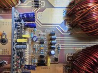
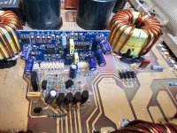
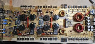
This subwoofer amplifier got 2 channels.
Seems like there are 2 seperate error measuring banks (driven by an sc3216 QA10).
One of those 2 banks measured an low amplitude output pwm switching at sc3216 Pin2 at 0v average.
The other bank measured the same pwm switching at 16v +-18v average.
Short after that both channels error banks sc3216 Pin2 goes to exact VCC DC voltage. I think they are internally connected when there is an error aplied.
When I ground Pin16 of TL494 to disable the error, the amplifiers output stage is happily switching. When applying a strong enough audio signal the pwm swichting becomes bad and the amplifier is making squeeking sounds.
Allthough this is not happening when the amplifier would go into protect. It would go into protect with clean switching.
Need to find out why that is happening.
Attachments
QA10 and QB10 are over-current protection.
Short after that both channels error banks sc3216 Pin2 goes to exact VCC DC voltage. I think they are internally connected when there is an error aplied.
^^^ That's the designation of the 3216?
Audio or PS PWM switching becomes bad?
Short after that both channels error banks sc3216 Pin2 goes to exact VCC DC voltage. I think they are internally connected when there is an error aplied.
^^^ That's the designation of the 3216?
Audio or PS PWM switching becomes bad?
- Home
- General Interest
- Car Audio
- Emphaser EA2500D schematics/component number