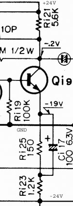
Missed the flurry of replies, sorry....here is the diagram I have been talking about. Hope this clarifies everything.
The difference between AC and DC gain is not much seeing the differences in magnitude - 1200 ohms vs 150 ohms. BUT - there is a small but insignificant change if the 150 ohms is shorted out.
Rc/Re would be overall AC and DC gain if Ce is not present. If Ce is present Rc/Re would be DC gain. Then AC gain would be Rc/re (Re is too large to take into consideration).
Attachments
Addendum: The AC gain would be Rc/re when Ce is present because it bypasses Re, not because it is too large. Getting distracted by other things here and I wrongly stated that Re would be left out because it is too large.
Well that clarifies everything.
The DC gain is not as high as the AC gain.
That is because re=~6r and Re=1k2 define the AC gain ~4.6x
and adding Re'=150r to that total defines the DC gain ~4.1x
re=~6r is based on ~4.3mA for Ic
The DC gain is not as high as the AC gain.
That is because re=~6r and Re=1k2 define the AC gain ~4.6x
and adding Re'=150r to that total defines the DC gain ~4.1x
re=~6r is based on ~4.3mA for Ic
Last edited:
Yes, you have all the values perfectly right. I replaced Re with 2k2. Before doing so, I removed the Ce cap and discovered that the distortion I heard went away. That was what made me decide that I would be better off turning the gain down. Now there is a 2k2 there. Everything else is the same. Gain is 2.6. Input impedance goes up as well.
Funny thing is, it plays louder at a lower volume setting now! These effects are of course in both channels. I will get this measured to see what is going on. In the meantime I am going to just keep using it, with possibly a 470uF for Ce. I like what I hear right now - it more than keeps up with present day opamp based units sonically.
Funny thing is, it plays louder at a lower volume setting now! These effects are of course in both channels. I will get this measured to see what is going on. In the meantime I am going to just keep using it, with possibly a 470uF for Ce. I like what I hear right now - it more than keeps up with present day opamp based units sonically.
So what's the purpose of the cap?
Such a large value may be a boot-strap used during large swings or turn-off?
Would it be possible to show a little bit more of the schematic?
Thanks
-Antonio
Such a large value may be a boot-strap used during large swings or turn-off?
Would it be possible to show a little bit more of the schematic?
Thanks
-Antonio
could it be that the power supply started motor-boating due to excessive DC gain?
Reducing the DC gain then improves the stability of the interaction between the Amplifier and the PSU.
Just a guess !
Reducing the DC gain then improves the stability of the interaction between the Amplifier and the PSU.
Just a guess !
I've heard motor-boating before, this did not sound like it. More like when SS's and cymbals hit it got distorted like bacon frying in a pan - best description I can think of here 😀 2k2 certainly fixed the issue.
Antonio, the cap reduces feedback and increases signal gain. The larger it is, the lower the frequency where it takes effect.
Antonio, the cap reduces feedback and increases signal gain. The larger it is, the lower the frequency where it takes effect.
Last edited:
I was not suggesting your amp is suffering LF instability.
I was raising the possibility that the designer reduced the LF gain to remove the possibility of LF instability with the combination of Amplifier and PSU that he used to develop the design.
I was raising the possibility that the designer reduced the LF gain to remove the possibility of LF instability with the combination of Amplifier and PSU that he used to develop the design.
Antonio, the cap reduces feedback and increases signal gain. The larger it is, the lower the frequency where it takes effect.
True, as discussed earlier, but I was curious as to why the designer added this large cap for such a small change in gain. I've seen numerous designs where the shunted resistor is at least the same resistance as the remaining series resistor, and some designs where a much smaller capacitor was used presumably for some added phase margin.
So its just another one of my why was it done that way curiosities?
A little more of the schematic and maybe we can put this curiosity to rest.
Thanks
-Antonio
I was raising the possibility that the designer reduced the LF gain to remove the possibility of LF instability with the combination of Amplifier and PSU that he used to develop the design.Yeah that maybe a possibility....
Here's a link to the schematic
http://www.fotoalbumet.com/u/00/24/40/files/Manuals/Model-700C_1.PNG
🙂
It did have those carbon resistors though I find it hard to believe that these would cause this much hf distortion. It's got metal films now in all feedback related areas.
Woops thats a commercial design, don't know the legalities of such. I think it best to let this one lay and let curiosity get the best of me.
Thanks for your efforts, hope it all works out for you.
-Antonio
Thanks for your efforts, hope it all works out for you.
-Antonio
Well, it is an obsolete model. It was in production around 40 years ago so I am not sure if anyone will pursue legalities now. If anything I have been trying to make it perform well - I have not really modified it, just changed a resistor value to stop it distorting. There are many factors in play here, certainly not faulty design - I am not really trying to find fault or change the essence of the design here.
When I considered buying it, I figured I will need a good tech who is willing to go the distance and a lot of dough or I could buy the measuring equipment myself and have even more fun executing the necessary steps, including gaining a better understanding of audio circuitry and design.
I've decided its best to go the second route. In the end I will have more than just that preamp. I certainly know the basics to do everything the right way so it does not look like someone botched up its innards. And I do not have a commercial interest.
Thank you all for participating in this thread - it has helped me a lot.
- Status
- Not open for further replies.
- Home
- Source & Line
- Analog Line Level
- Emitter bypass caps in a CE stage