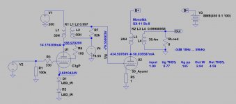
Here is how I see the schematic. That said, I am trying to eliminate the signal going thru a coupling cap and resistor. The way I see it, I need to change the Aa driver to a lower Rp driver so an IT can be used. Or, direct connect. Does this sound correct?
Attachments
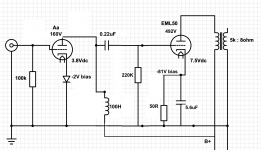
There are some things in your schematic you could take a look at:
- a grid stopper on both tubes
- A dropper resistor and cap between B+ and plate choke/IT. I suggest a DC Link final capacitor, something over 10uF.
- a larger cathode bypass cap on the 50, e.g. 50uF.
- the Aa is directly heated - you have drawn an indirectly heated tube. Are you going to use Rod Coleman filament regs or what?
The bias on the input tube is unclear - what gives you the 2v?
Did you mean to post a revised schematic?
Back a few posts euro21 suggested one of Ale's gyrators. That might work with the Aa. He sells the PCBs so you'd have to build it and test it.
.
Last edited:
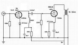
With 100H inductance the "last" frequency where
Z=2*Ri
is met: 95Hz.
Below it the load impedance is lower, so distortion growing.
p.s.
I hope that 50R is typo.
Z=2*Ri
is met: 95Hz.
Below it the load impedance is lower, so distortion growing.
p.s.
I hope that 50R is typo.
Last edited:
euro21: updated schematic should have indicated 50K, good catch. I am likely not pursuing much further the Aa --> EML50. Will be looking for a new driver tube or going back to the C3g.