Dear all,
I tried to find something on Internet to help me. Till now - nothing, so I decided to ask you.
What is problem?
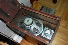
I have elliptic speaker (really big). It's about (approx.) 24 cm x 14 cm and I can say that this unit works fine. Now is mounted (perhaps you can see in my pictures) in small boxes. It works, but I would like to create something better.
Question: Is there any good project or anything what is done here on DIY group that can be used in my case? I really want to take the most from this unit because this cabinet is not enough for it. HF speaker is not a problem now.
There is no marks on it, so I cannot say parameters of unit.
Please help me if you can. This project can be anything: compression, bassreflex, horn, transmission - ANYTHING. I'll appreciate any explanation or suggestion what to use or what to build for this driver, because this cabinet is baaaaddd...🙁
Many thanks in advance,
Boris
I tried to find something on Internet to help me. Till now - nothing, so I decided to ask you.
What is problem?
I have elliptic speaker (really big). It's about (approx.) 24 cm x 14 cm and I can say that this unit works fine. Now is mounted (perhaps you can see in my pictures) in small boxes. It works, but I would like to create something better.
Question: Is there any good project or anything what is done here on DIY group that can be used in my case? I really want to take the most from this unit because this cabinet is not enough for it. HF speaker is not a problem now.
There is no marks on it, so I cannot say parameters of unit.
Please help me if you can. This project can be anything: compression, bassreflex, horn, transmission - ANYTHING. I'll appreciate any explanation or suggestion what to use or what to build for this driver, because this cabinet is baaaaddd...🙁
Many thanks in advance,
Boris
Attachments
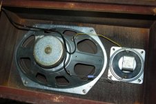
They look nice , like the old Pioneer for car ,yet they had a soft surround from coated silk .
Definitely worth a try , with or without the tweeter ( change the cap !! ) and on another baffle , mounted on the panel and not behind it . It could become a nice mid-wf in a multi-way system , but that's dreaming ...😱
Definitely worth a try , with or without the tweeter ( change the cap !! ) and on another baffle , mounted on the panel and not behind it . It could become a nice mid-wf in a multi-way system , but that's dreaming ...😱
Yeah, thank you for the suggestion.
I'll change the cap (now is electrolytic 4,7 uF).
But I have suggestion from one guy that I should replace it with:
1. Non-polarized MKP, MKT or MKS (2,2 to 4,7 uF) or
2. Bipolar electrolytic 2,2 - 4,7 uF
What is acceptable or suggested or right to install here on this position instead of faulty electrolytic cap ?
Regards,
Boris
I'd suggest that you mount them on Open Baffle, supported by a 15" high Qts woofer (think Alpha 15) and you may get a nice sound for little money...
Hi,
The rear of the box appears to have two large open slots ?
Probably why the box doesn't seem to work well.
Without driver parameters its difficult to suggest a plan.
rgds, sreten.
The rear of the box appears to have two large open slots ?
Probably why the box doesn't seem to work well.
Without driver parameters its difficult to suggest a plan.
rgds, sreten.
Yes, indeed.
2 large holes. I have another suggestion to close them with wood or any other material and put some dumping material inside of cabinet to check is the sound better that earlier.
But - question remains. Is there any better way to use elliptic unit.
Thanks,
Boris
2 large holes. I have another suggestion to close them with wood or any other material and put some dumping material inside of cabinet to check is the sound better that earlier.
But - question remains. Is there any better way to use elliptic unit.
Thanks,
Boris
you could try to tune the box..if you can get your hands on a generator. Would need new back and PVC or carboard tubing. Also a way to cut a hole in the new back - for the tubing.
Hi,
FWIW they seem quite old. The bass driver is a decent size but not really big.
Its surround suggests it is not a particularly low Fs driver. The cabinet design
appears fairly clueless. Yes you should stuff the box with wadding.
Presumably forget about vented alignments. Close off the slots with a
temporary extra back. See what that is like. If its too boomy but a lot
more bass than standard then try aperiodic loading. Remove the back
(temporary) and add glued layers of felt to the back keeping glue away
from the slots until it sounds about right.
Alternatively build a pair of floorstanding cabinets about twice the current
box volume and use them sealed and well stuffed, they should be OK.
TBH I'm not sure they are worth the effort of new cabinets, YMMV.
rgds, sreten.
You should start with a coil in series with the woofer , so it will prevent cone break-ups and will introduce you to the famous baffle step , so it will be a real speaker !
You will get immediate benefits by removing the cloth and mount the
drivers frontally , as there won't be any more diffraction caused by the
edges of the cut .
This has to be done first ; second , while doing this , check if the wood
is ok , some chipboard may become friable after many years 😱
You will get immediate benefits by removing the cloth and mount the
drivers frontally , as there won't be any more diffraction caused by the
edges of the cut .
This has to be done first ; second , while doing this , check if the wood
is ok , some chipboard may become friable after many years 😱
As an inverterate tinkerer I would play with the original box a little first.
First tho, check the speaker surround for tears/rips and holes.
Add cleats along the panel joins with wood glue but do not spend too much cash on this.
Then glue some small scraps of MDF on the panels, again do not spend too much.
Then place some polyester wadding and some fibreglass in the box, put the back on and listen. If there is an improvement I would stop there unless you have a spare 10 inch woofer floating around and want to build a box; to add a .5 bass boost
A resonant box is a way of getting enough bass extension with these kind of vintage drivers
Check this web page for some examples:
Contents
However, I agree that the speaker you have does not really worth the effort.
If you like the sound of your speaker and want to upgrade,
you might check German ebay for alnico Saba or Isophon drivers (oval or round).
Your oval is a similar driver but is not alnico magnet. (your tweeter is alnico though)
If you want to build something good, it is worth spending an extra 40-60 euros for the alnicos.
I have compared side by side alnico and ferrite vintage speakers and the difference is very significant.
This is quite an interesting old speaker! 🙂
It probably works best with a valve amplifier giving a nice tone. Sound waves being allegedly round, LOL, elliptical was not hugely popular. 😉
eBay Guides - Rare EMI speaker chassis, oval elliptical, tweeter, B W
The box is quite likely OK, but some wadding would do no harm. Bass loading is dominated by the stiff corrugated surround with a high Qb, hence the open back. I would measure the bass resistance which could be anything between 4 and 16 ohms, and add a 10W wirewound series resistor of about half that for a valve tone with a transistor amp. This is to simulate the output impedance of a valve amp. Renew the capacitor by all means. See how it sounds. The sealed tweeter probably crosses over quite low at about 1kHz.
This sort of elliptical driver was almost standard in old radiograms and sounded very warm and nice. You could grow to love it.
An externally hosted image should be here but it was not working when we last tested it.
It probably works best with a valve amplifier giving a nice tone. Sound waves being allegedly round, LOL, elliptical was not hugely popular. 😉
eBay Guides - Rare EMI speaker chassis, oval elliptical, tweeter, B W
The box is quite likely OK, but some wadding would do no harm. Bass loading is dominated by the stiff corrugated surround with a high Qb, hence the open back. I would measure the bass resistance which could be anything between 4 and 16 ohms, and add a 10W wirewound series resistor of about half that for a valve tone with a transistor amp. This is to simulate the output impedance of a valve amp. Renew the capacitor by all means. See how it sounds. The sealed tweeter probably crosses over quite low at about 1kHz.
This sort of elliptical driver was almost standard in old radiograms and sounded very warm and nice. You could grow to love it.
One thing you DO have to be very careful of tho, these were made when maximum power for amplifiers (and radiograms ) was about 5 to 12 watts, these older drivers are very easy to overdrive with modern transistor equipment. I should know I have destroyed quite a few at parties over the years
Yes, I don't suppose the old valve radiogram my parents had was more than 5 watts, but it filled the room with stunningly realistic human voices on LP and radio! 😀
I think they only had about 5 records, including "My Fair Lady" with Stanley Holloway and Audrey Hepburn singing. Loved the tone. It died when the bitumen-insulated transformer caught fire, filling the room with black smoke.
Bass and treble was very gently rolled off, but those old valves could do the business. My suggestion of the series resistor is a serious one. It brings back the essential lovely tone these sort of speakers had. 😎
It probably isn't really all that old, 1970??
Ceramic magnet
Although some of you would say that was an age ago.
Ceramic magnet
Although some of you would say that was an age ago.
It probably isn't really all that old, 1970??
Ceramic magnet
Although some of you would say that was an age ago.
Quite agree. But in that transistion period between valves and transistor. I'd reckon only a valve amp would do these speakers justice. 😀
Elliptical is currently unfashionable, but has a lot going for it in terms of resonance. That old Golden Ratio of 1.616:1 that applies to cabinets too. 😎
EMI ellipticals had a solid following in the early seventies, especially for efficiency. Stiff corrugated surrounds were OK with valve amps, which are a bit woolly on bass control.
Thank you all people...
I didn't have enough time for all mentioned experimenting, but I have changed HF unit (bad unit is changed with CORAL HF and electrolytic cap of 4,7 uF is replaced with nonpolarized 3,3 uF. Much better high frequencies.
Further - I opened cabinet and it seems that the whole picture is better than closed / vented option. I will check the sound in next few days.
Once again - thank you for all suggestions, regards,
Boris
@system7
Dear Mr.,
Please clarify if you can...What does it mean: ...10W wirewound series resistor of about half that for a valve tone with a transistor amp?"
10W wirewound series resistor is clear, but what do you mean anout half that for a valve tone with a transistor amp ?
Speaker impedance is 4 Ohms, approx P is about 10-20 W. No marks on it.
Thanks
Boris
I thought I explained it simply enough. With a 4 ohm speaker you add a 2-4 ohm series resistor to simulate a valve amplifier. Based on Thevenin equivalent:
Baas response and crossover is affected slightly.
With a paper bass, you will do well to use a paper tweeter if you must replace. These cone tweeters should integrate nicely:
Visaton - Lautsprecher und Zubehör, Loudspeakers and Accessories
Visaton - Lautsprecher und Zubehör, Loudspeakers and Accessories
Best to use a matched pair, of course. Unmatched tweeters not good.
An externally hosted image should be here but it was not working when we last tested it.
Baas response and crossover is affected slightly.
With a paper bass, you will do well to use a paper tweeter if you must replace. These cone tweeters should integrate nicely:
Visaton - Lautsprecher und Zubehör, Loudspeakers and Accessories
Visaton - Lautsprecher und Zubehör, Loudspeakers and Accessories
Best to use a matched pair, of course. Unmatched tweeters not good.
- Status
- Not open for further replies.
- Home
- Loudspeakers
- Multi-Way
- Elliptic speaker - what to do with...?