Right, fully understood guys - thank you very much for your brilliant advice here. I have a replacement smoothing 32+32uf cap on the way, when it arrives I will also fit 4 1N4007s in a bridge, try a 200ohm resistor with it and mount the transformer on rubber. Hopefully it doesn't blow up in my face!
Hi richardleonard,
There is an excellent forum VintageRadio.co.uk who have dozens of threads just on this record player. That could be worth a visit ...
Elixabethan Pop-ten
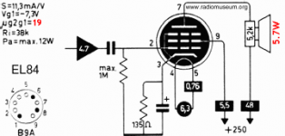
I also think you should try and get voltages from all the pins on the EL84 - using AC for the heater pins (4, 5, clockwise from underneath). It will be a useful reference for the other changes you are planning.
There is an excellent forum VintageRadio.co.uk who have dozens of threads just on this record player. That could be worth a visit ...
Elixabethan Pop-ten
I also think you should try and get voltages from all the pins on the EL84 - using AC for the heater pins (4, 5, clockwise from underneath). It will be a useful reference for the other changes you are planning.
Last edited:
The filter cap has nothing to do with the problem. The issue is the half-wave rectification.
Substituting a bridge rectifier would be the ideal fix, but there may be obstacles, like too much output voltage (easily fixed) or connection/low insulation of the secondary "cold" to the chassis or screen.
Anyway, the original arrangement worked at some point in the past, and this could be replicated: by tightening the bolts of the transformer if any, or crimping the holding bracket harder if it is an economical construction.
Impregnating the laminations with a varnish, resin or two-components vitrification compound for parquets could also help
Not quite: higher mains voltage is a non-issue, especially if the OP lives in the UK.
Now, all the european mains voltages have been harmonized at 230V, but the new limits include the old tolerances for each country, thus a higher voltage shouldn't be present, especially in the UK where the centre value was 240V.
In fact, appliances should on average see a lower voltage. Not a general rule, and there might be exceptions, but if this equipment sees a higher voltage than it was designed for, it means the utility company contravenes the terms of contract
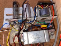
I live in the UK! Thank you so much everyone for the help here. I'm pleased to say that I didn't have to wait for the 1n4007 diodes as I was able to take an adequately rated bridge off a scrap psu board from something else. The old metal rectifier made a perfect mounting platform for it 🙂. I also fitted rubber to the underside of the transformer and the buzzing is totally gone!
Sadly though - there is absolutely no sound. I'm presuming it must be the EL84 as both transformers work, the caps are fine, resistors fine, pots fine, connections from deck fine. So I'm thinking I should replace the EL84 and then hopefully the repair will be complete.
Sadly though - there is absolutely no sound. I'm presuming it must be the EL84 as both transformers work, the caps are fine, resistors fine, pots fine, connections from deck fine. So I'm thinking I should replace the EL84 and then hopefully the repair will be complete.
Attachments
Check the wiring, filament also, and measure dcV,.
EL84 is easiest to change, but least probable reason.
EL84 is easiest to change, but least probable reason.
Last edited:
DcV at bridge is 237vdc
I've checked all wires which seem fine, i've also checked continuity from the cartridge terminals all the way to where the audio cables connect to the front right potentiometer of the deck. Any other thoughts before ordering an EL84?
I've checked all wires which seem fine, i've also checked continuity from the cartridge terminals all the way to where the audio cables connect to the front right potentiometer of the deck. Any other thoughts before ordering an EL84?
Are you able to measure the voltages on the pins of the EL84? Pins 4&5, seen from underneath and counting clockwise, should be measured in AC, the others DC from a ground point.
Hey, thanks for the quick reply!
Pin 1 - NC
Pin2 - 0v
Pin3 - 4.7vdc
Pin4&5 - 5vac
Pin6 - NC
Pin7 - 220vdc
Pin8 - NC
Pin9 - 209vdc
Pin 1 - NC
Pin2 - 0v
Pin3 - 4.7vdc
Pin4&5 - 5vac
Pin6 - NC
Pin7 - 220vdc
Pin8 - NC
Pin9 - 209vdc
What are the voltages across the terminals of the OPT? No crackles or hums indicates a loose connection, or maybe an issue with the wiring of the volume control.
DC IN to the OPT = 229vdc
AC OUT of the OPT = 0.6vac
Probing the outputs of the OPT does nothing to the sound, probing the inputs creates a very subtle crackle out the speaker. Dead transformer?
EDIT: If it is useful - resistance across OPT input is 320ohm, across output is 0.6ohm
AC OUT of the OPT = 0.6vac
Probing the outputs of the OPT does nothing to the sound, probing the inputs creates a very subtle crackle out the speaker. Dead transformer?
EDIT: If it is useful - resistance across OPT input is 320ohm, across output is 0.6ohm
Last edited:
Have a look at the input side of the circuit.
Sorry, would you mind being a little more specific here?
Pick up, Vol control, wiring to the grid - it has been said before.
If you touch the grid do you have hum (careful not to touch high
voltage points).
If you touch the grid do you have hum (careful not to touch high
voltage points).
Pick up, Vol control, wiring to the grid - it has been said before.
If you touch the grid do you have hum (careful not to touch high
voltage points).
I've probably misunderstood something but I think i've already checked and posted all this?
I've checked continuity from pickup to amp, i've checked all wiring to and from both from pots, i've tested that both pots function correctly with resistance check while turning. I've checked inputs and outputs of OPT and mentioned a mild crackle/hum when probing the inputs but not outputs. I've checked all the pins on the tube and posted results, slight hum when probing pin 2.
it was working before you made some changes.
Erm... about that, I think my first post was slightly wrong. It was given to me by a friend who said it sounded good when it was last used about 5 years ago. I never tested it with a record since getting it because of the buzzing transformer - I didn't want to leave it on for very long in case it smoked up. I elected to clean up the deck and deal with the buzzing before testing it. So while i reported it sounded good, that was based on what he told me - it's entirely possible that the sound was also gone prior to dealing with the buzzing transformer.
- Home
- Amplifiers
- Tubes / Valves
- Elizabethan Pop Ten restoration