F-2425: I hope the two dots next to the narrow board section in quadrant B1 do not already indicate a wire link between the two sections, otherwise the wire would be redundant.
I appreciate the markup of the board traces. To answer your question about the two dots - they actually are solder pads where I imagine a wire could have been installed at the factory - but wasn't. I've attached a photo.
I haven't had much of an issue with hum but I'm planning to implement your proposed gain modification; I just need to place an order for some parts. And an X-acto knife in case I need to cut the small traces as you suggested.
I'm also going to replace the 4.7Kohm trim pot on the F-2428 board. There's a lot of oxidation on the legs and I have replaced the other ones throughout the receiver with Bourns multi-turns so I might as well get this one also.
Once again I appreciate the time you've put into your replies and I'll update the thread once I have implemented the gain modification.
Attachments
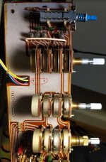
These might come in handy then. A small drill may be useful, the holes don't look super big as-is.I appreciate the markup of the board traces. To answer your question about the two dots - they actually are solder pads where I imagine a wire could have been installed at the factory - but wasn't. I've attached a photo.
Looks like current should be low enough for a multiturn, maybe a milliamp. Unlike single turn pots, they are not designed to carry substantial current, which becomes an issue when you try to replace the trimpot in an oldschool diode string bias setup.I'm also going to replace the 4.7Kohm trim pot on the F-2428 board. There's a lot of oxidation on the legs and I have replaced the other ones throughout the receiver with Bourns multi-turns so I might as well get this one also.
Looking at the power amp circuit, it seems we have a quasicomplementary output predating the use of a Baxandall diode. I would consider implementing one, but that'll take some simulation first...
In the preamp, try shunting the first, second and third transistor bases to ground one by one with 1 uF capacitor. This may help to identify source of the problem.
Regards,
Regards,
Thank you both for the replies.
I did some research on the Baxandall diode - there are some examples on AK of folks doing this mod with other Sansui amps. I'll look into it some more.
@mandu - I will try this and let you know what I find!
I did some research on the Baxandall diode - there are some examples on AK of folks doing this mod with other Sansui amps. I'll look into it some more.
@mandu - I will try this and let you know what I find!
Hey folks,
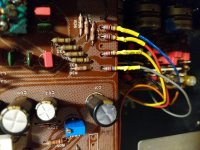
Quick update here: I implemented the gain modification suggested by sgrossklass and it worked great. I can now only hear a slight hiss from very close to the speaker and the useful range of the volume control has been improved. There's no audible hiss whatsoever from the listening position. I'm very grateful for the suggestion!
I haven't had the opportunity to try the other suggestions yet - have family in town for Thanksgiving - but just wanted to update the thread and say thanks again.
I attached a photo where you can see the 47K resistors in-line with the outputs of the tone control board and the new 10K resistors to ground.