Some power amp designs eliminate the capacitor in the series feedback path because a good quality capacitor in this critical position needs to have a large value and can therefore be expensive. A DC servo is then used to control the DC offset voltage at the output.
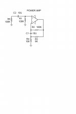
A friend of mine has used the circuit below many years ago. It allows the use of a smaller capacitor (C1) which can then be MKP or similar. R3 must be much smaller than R2 to get a good -3 db at low frequencies. For this reason the circuit works best with FET's in the diff amp. However, useful LF extension can be achieved with BJT's in the diff amp if they are matched and R1 and R2 are precision resistors.
While tweaking a Sony TAF-444ESX amp I noticed that it uses this circuit with a a dual JFET input pair. The capacitor was formed by two 47uF Muse elctrolytics connected in non-polar mode. Although the caps were inside the feedback loop, sound quality still improved when I replaced it with a 10u polycarbonate.
I wonder why this circuit is not used more often since it can eliminate that dreaded electrolytic cap in the feedback circuit. Does anybody have experience with this circuit?
Attachments
If not cost, I don't know why anyone would put an electrolitic in the signal or feedback path to begin with. They typically sound sour. Is there any other reason?
Almost everyone puts an electrolytic in the feedback loop. The reason is that it is cheap and effective. Servos, properly designed, are better. Some extreme friends of mine, choose to direct couple, without servos, and live with the voltage drift on the output. This is not easy, most of the time.
Hi,
The schematic appears to show a DC gain of about x51 and an AC gain of about x1001. Am I correct?
If so then the amp will generate large DC offsets due to small dc on the input.
regards Andrew T.
The schematic appears to show a DC gain of about x51 and an AC gain of about x1001. Am I correct?
If so then the amp will generate large DC offsets due to small dc on the input.
regards Andrew T.
To calculate AC gain short C1:
AC_GAIN=((R2//R3)+R4)/R4, it is about 51
To calculate DC gain remove C1:
It is then a unity gain voltage follower if the input is applied at R1, howeever the usual DC decoupling cap C2 prevents DC response. At DC R3 in series with R4 acts as an output load.
R1=R2 minimizes ofsett voltages.
AC_GAIN=((R2//R3)+R4)/R4, it is about 51
To calculate DC gain remove C1:
It is then a unity gain voltage follower if the input is applied at R1, howeever the usual DC decoupling cap C2 prevents DC response. At DC R3 in series with R4 acts as an output load.
R1=R2 minimizes ofsett voltages.
The DC gain is actually 1!AndrewT said:Hi,
The schematic appears to show a DC gain of about x51 and an AC gain of about x1001. Am I correct?
 but you have two breakpoints, the last one gives you gain of 1.
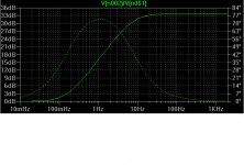
LTSpice Simulation using an op-amp model with input decoupling omitted
The 3-db freq is at 7.8 Hz for the component values posted.
For a JFET input stage R1 and R2 can be increased to 1M to give a -3 db freq of 0,78 Hz.
To improve the low freq cut-off for a BJT input pair R1 and R2 can be increased, but output offset may become an issue. An alternative is to lower R3 and R4. If power dissipation becomes an issue, resistors can be paralleled.
Attachments
Hi,
thanks for explaining the gain.
Q how do you calculate the time constants?
Q is it a 2 pole bass roll off with staggered freqencies?
regards Andrew T.
thanks for explaining the gain.
Q how do you calculate the time constants?
Q is it a 2 pole bass roll off with staggered freqencies?
regards Andrew T.
One of Rod Elliot's articles, perhaps the most recent, discusses the subject. He based it on some SPICE simulations. His conclusion (I won't try to summarize the agument) was that the elimination of this cap can have unpleasant/unfortunate results when certain events occur in the input source.
I don't know enough to say if he is right or wrong, but I think anyone contemplating yanking the cap should at least check it out.
I don't know enough to say if he is right or wrong, but I think anyone contemplating yanking the cap should at least check it out.
Hennie said:The 3-db freq is at 7.8 Hz for the component values posted.
and though it is out of audio range it is still too much- this will bring some phase distortion at LF- not good cause stability/delay issues.
To make border freq. lower should be used bigger resistors, which makes it unable to use in bipolar differential stage.
Hi,
If the input stage is a pair of complementary LTPs, then will the high impedance necessary for this circuit be less of a problem for BJTs?
In other words will the bias flow from the upper base to the lower base and only a tiny residual current flow to ground? This implies a small offset voltage at the input and at the inverting input.
All comments gratefully received.
regards Andrew T.
AndrewT:
I have used that circuit in a power amp but had to do a few things to get an acceptable low frequency cut-off and output offset voltage:
Indeed as you say a complementary input LTP helps a lot. I just matched the DC HFE of all transistors to minimize the difference DC currents flowing through the high value resistors R1 and R2. But note that the DC offset can actually be worse with a complementary LTP input if the transistors are not matched. The voltage drop across R1 and R2 decreases, but the difference in voltage drop may actually increase giving a higher output offset. (That is if the base currents add the wrong way). I also glued them to a common aluminium strip to ensure better thermal tracking, but I have not done an analysis to make sure this is really necessary.
Other things I did:
Paralled two 10u caps for C1
Made R3 and R4 25% of the posted values by using a parallell combination for R3.
This gave me a -3dB of approximately 1Hz which was acceptable.
With bipolars the relatively high R100k values will cause an increase in LF noise (< 1Hz) compared to the lower values normally used, but I did not find that to be a problem.
Andrew, the circuit is first order with a single pole at the -3dB point and a zero at a much lower frequency which levels the slope again at very low frequencies. Therefore it behaves in a similar fashion to the normal series feedback circuit - the breakpoints are just shifted to the lower frequency side. I did not derive the equation for calculating the breakpoints. My late friend Piet Krige did that many years ago, but I lost that piece of paper. It's easy enough to derive the equation for an idealised opamp model and I will post it later.
Upupa Epops
I see you have used that circuit already. With the FET input opamp LF noise will probably not be an issue here either. Anything else that you want to add from experience? I want to build a new power amp with a bipolar LPT input and I am considering this circuit.
What I want from this experience ? This circuit I am using in simple preams, concrete this schematic is so called " active cable " for connection between source and preamp. It give very well " sonic " results, much more better than " classical connection ". In PA I am rather using DC servo.
I see what you intend doing with the active connection. Contact degradation is something I have experienced. I clean my contacts regularly but even if gold plated they do seem to deteriorate due to pollution and I think it is audible, but it may just be my imagination. But how does contact deterioration affect the feedback in your circuit?
Back to the LF issue. Why do you prefer the DC servo?. I was always afraid of injecting unnecessary noise into the circuit. Have you published DC servo circuits I can search for? I did have one circuit of a Creek amp, and another of an Arcam Black Box DAC that I can trace out.
Back to the LF issue. Why do you prefer the DC servo?. I was always afraid of injecting unnecessary noise into the circuit. Have you published DC servo circuits I can search for? I did have one circuit of a Creek amp, and another of an Arcam Black Box DAC that I can trace out.
Although the caps were inside the feedback loop, sound quality still improved when I replaced it with a 10u polycarbonate.
Yes they are indeed inside the feedback loop. BUT they are in the feedback branch. As long as there is enough excess gain in the forward path, the behaviour of the complete NFB arrangement is dominated by the properties of the feedback network (this is a little simplistic, I know but still not incorrect) in terms of gain-setting and frequency response. Its properties do also greatly influence THD since any distortion in the feedback network actually CONTRIBUTES to the overall distortion rather than being reduced.
That's why you hear a larger improvement than you first expected.
And that's also why we want to avoid active components in the feedback path, and if we have no other choice than doing so (i.e. when we want to use a servo for instance) that we make a careful component choice.
Regards
Charles
To Hennie : Ask about contact degeneration somebody from profesional area - do you mean, that in some studio exist somebody, who is periodicaly cleaning contacts 😀 ? Or do you mean, that in Space Shuttle are all connection soldered ? And about DC servo : correct designed circuit have insignificat noise " contribution " 😉 . Look at pages of Erno Borbelly.
Epupa,
I just wanted an opinion on the issue of contact degeneration. My system uses gold plated jacks and connectors, but everytime I unplug and re-plug after it has stood unattended for a while, it seems to sound somewhat better. I noticed that when I wipe the contacts a residue comes off. Probably the result of air pollution.
Thanks for the reference to Erno Borbelly's pages. I will study the DC servo in more detail, but currently I am leaning towards what phase accurate has said, i.e. to keep the feedback path simple and use high quality components. From experience I tend to believe this is one of the most critical areas in terms of sound quality provided everything else is competently done.
With a previous design I also ensured that the components in the feedback loop is mechanically damped.
- Status
- Not open for further replies.
- Home
- Amplifiers
- Solid State
- Eliminating capacitor in amplifier series feedback loop