OK, thanks to both of you.
Gootee, i definitely do not have golden ears, and i am convinced that i know my soundmaterial very well. But your mentioned 0.5dB is to low, that i really could hear that difference, that's true. Rather i have to clean my ears at first then to blame the caps. Probably it's an imagination based of the expectations i had.
Best regards
artQuake
Gootee, i definitely do not have golden ears, and i am convinced that i know my soundmaterial very well. But your mentioned 0.5dB is to low, that i really could hear that difference, that's true. Rather i have to clean my ears at first then to blame the caps. Probably it's an imagination based of the expectations i had.
Eva, when i compare the noise @ the tweeters before and after i added the LP-Filter, i must say that it is superquiet now. Do you really think that this could generate bigger sound image out of this ? An Eva joke ? BTW: Great tip, i'll try to simulate the LP-Filter with altium next ...Maybe you were finding pleasant the disturbance produced by ambient RF on the input stage of the chip amp...
Best regards
artQuake
Don't forget that output impedance of the source changes the roll off point. If it's a bit high (like a volume pot) then you could have more roll off than the 1k suggests.
Thanks megajocke, thats what eva also mentioned
So in the present test i had a tube preamp output to the pair of LM3886's, so it would make sense that the cutoff is lower then when used with a Line driver. At the end i'll use a DRV134 with 1nF as LPass.
artQuake
Chose a value to get -0.x dB or so at 20Khz, it may be 2.2nF if the input is driven directly from a low impedance source like that DRV IC, 1nF if it's driven from 1k, etc...
So in the present test i had a tube preamp output to the pair of LM3886's, so it would make sense that the cutoff is lower then when used with a Line driver. At the end i'll use a DRV134 with 1nF as LPass.
artQuake
You could try just decreasing the cap to maybe 220p or so and replace the 1k with a 10k resistor - this way cutoff freqency will be the same but won't depend as much on input impedance. If you add a buffer then you won't solve the problem as the buffer needs to be protected from the RF too.
Aaahm 
If i add a LP before the Amp why it wont solve the problem ? BTW the Line Driver is placed in the enclosure of the preamp.
The BPA's are disconnected at the moment, while i am working on the PSU Enclosures. So i have only the possibility to test your statement with the biamped LM's.
But could I test this also like as follows ?
Left (+) Out of Balanced Line Driver -----> Left in Amp LM3886
Right (+) Out of Line Driver -----> Right in Amp LM3886
Where to connect the (-) Outs of Balanced Line Driver while i test this ? Let them unconnected ?
And then test if the light switches still act on the Amp. Somehow illogical, because it should work anyway due to the LP-Filter at the Input of the Amp .... ?😕
?😕
If you add a buffer then you won't solve the problem as the buffer needs to be protected from the RF too.
If i add a LP before the Amp why it wont solve the problem ? BTW the Line Driver is placed in the enclosure of the preamp.
The BPA's are disconnected at the moment, while i am working on the PSU Enclosures. So i have only the possibility to test your statement with the biamped LM's.
But could I test this also like as follows ?
Left (+) Out of Balanced Line Driver -----> Left in Amp LM3886
Right (+) Out of Line Driver -----> Right in Amp LM3886
Where to connect the (-) Outs of Balanced Line Driver while i test this ? Let them unconnected ?
And then test if the light switches still act on the Amp. Somehow illogical, because it should work anyway due to the LP-Filter at the Input of the Amp ....
?😕Okay, that would work. I thought you meant putting it inside the poweramp. Those drivers have floating outputs so the negative output should be connected to ground if you try to drive an unbalanced input - they try to simulate a transformer output. Output impedance will be high otherwise.
artquake said:OK, thanks to both of you.
Eva, when i compare the noise @ the tweeters before and after i added the LP-Filter, i must say that it is superquiet now. Do you really think that this could generate bigger sound image out of this ? An Eva joke ? BTW: Great tip, i'll try to simulate the LP-Filter with altium next ...
Best regards
artQuake
RF results in noise because the amplifier circuit mirrors these frequencies back into the audio range and above. RF also results in little distortion when the amplifier is being fed with audio at the same time. I think that what you are experiencing now is in part a quieter system and in part placebo effect 😉
The cutoff that I recommended is indeed quite low, you may consider increasing it, but bear in mind that when you listen to CDs any frequencies above 20Khz reaching the amplifier input will be only distortion products.
Matching the capacitors is recommended when the cutoff is low in order to get equal group delays.
There is a reason that National recommends bypassing the power supply pins with 100nF X7R ceramic capacitors -- EMI and RFI -- these chips have pretty long legs (antennae). Your servo will also like to be bypassed.
You can also put a small (some hundreds of picoFarads) across the inputs of the LM4780.
You should also check the soldering on your input connections, and on the cables you are using. Any oxidation on the signal lines or power lines will help demodulate an RF signal.
You might also want to put a ferrite bead on the input lines. This is very, very effective.
So, before altering the signal channel, I would do the basic blocking and tackling of the soldering, power supply and input.
@Eva
Why ? Because of the phase shift the LP-Filter creates ?
@jackinnj
Each PA100 Board has one 1000uF, 100 uF, 10 uf, & finally 0.1 uF per supply rail. The 0.1uF's are even Kemet X7R and they are mounted on the backside of the pcb at the legs of the LM4780.
So why and how to implement a LP-Filter for the servos ?
Thanks in advance for all recommendations
artQuake
you may consider increasing it, but bear in mind that when you listen to CDs any frequencies above 20Khz reaching the amplifier input will be only distortion products.
Why ? Because of the phase shift the LP-Filter creates ?
@jackinnj
bypassing the power supply pins with 100nF X7R ceramic capacitors
Each PA100 Board has one 1000uF, 100 uF, 10 uf, & finally 0.1 uF per supply rail. The 0.1uF's are even Kemet X7R and they are mounted on the backside of the pcb at the legs of the LM4780.
That's interesting. The servos use the same supply. To reduce the voltage from 35 VDC to 15VDC (NSC LF412ACN) i use a DC/DC Converter (Traco Power TEN 5-4823WI ). I put 0.1 uF's at the Input and the output of that converters (each AMP channel has it's own). To my knowledge that servo circuit runs anyway around 7 Hz.Your servo will also like to be bypassed.
So why and how to implement a LP-Filter for the servos ?
How does that look like ? Where ? Just after entering into the enclosure of the Amp or more near to the Amp Boards ? In how it is very effective ?You might also want to put a ferrite bead on the input lines. This is very, very effective.
Thanks in advance for all recommendations
artQuake
LP filters don't just introduce a phase shift, they introduce a small signal delay across the entire passband. For a first order, the delay is roughly 1/4 wavelenght of the -3dB frequency, and it vanishes above that frequency. If delay mismatch is too big, imaging may shift. This is unlikely to happen for a filter having the -3dB above 70Khz, though, but for the sake of perfectionism...
Be very careful with parallel capacitors. I have done many measurements on real capacitor combinations and only a small fraction of them are advantageous. The most usual result is heavy ringing on the supply rails (that may be then trigeered by RF at the input of the amplifier...). The most troublesome capacitors when paralleling are big low-ESR electrolytics and big films, fortunately you have medium-sized electrolytics too that may hopefully act as dampers.
Be very careful with parallel capacitors. I have done many measurements on real capacitor combinations and only a small fraction of them are advantageous. The most usual result is heavy ringing on the supply rails (that may be then trigeered by RF at the input of the amplifier...). The most troublesome capacitors when paralleling are big low-ESR electrolytics and big films, fortunately you have medium-sized electrolytics too that may hopefully act as dampers.
Eva, i simulated the LP-Filter Circuit on Signal as it's on revised schematic with 1nF//1nF to Signal GND.
(The first two curves are the inverted and non inverted signal from the generator, and the third and fourth are the curves after LP-Filter)
In that way
The PSU is similar to the one of Dejan Veselinovic (TNT-Audio)
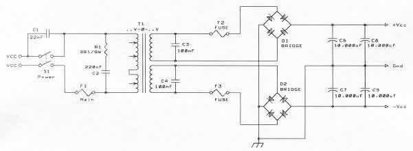
up to now without the 100NF between the bridges.
After these caps i go directly to the DC-Socket and there via 6 x 1.5 mm² (3 mm² per Rail lenght max. 0.5 m) power cable from both PSU's to a separate Power Input Socket of each channel to Amplifier housing. from there directly to the mentioned Supply Caps of the Amp Boards.
Is there any objection to this ?
An externally hosted image should be here but it was not working when we last tested it.
(The first two curves are the inverted and non inverted signal from the generator, and the third and fourth are the curves after LP-Filter)
In that way
that's true.they introduce a small signal delay across the entire passband
Medium sized ? The PSU Cap's i use are F & T Cap Typ GW.The most troublesome capacitors when paralleling are big low-ESR electrolytics and big films
The PSU is similar to the one of Dejan Veselinovic (TNT-Audio)
up to now without the 100NF between the bridges.
After these caps i go directly to the DC-Socket and there via 6 x 1.5 mm² (3 mm² per Rail lenght max. 0.5 m) power cable from both PSU's to a separate Power Input Socket of each channel to Amplifier housing. from there directly to the mentioned Supply Caps of the Amp Boards.
Is there any objection to this ?
Eva said:Maybe you were finding pleasant the disturbance produced by ambient RF on the input stage of the chip amp...
When trying circuits for my headphones (which sound a bit dark) I liked a certain assembly. When checking with a scope I realized, that the circuit superimposed some local oscillation on the output waveform. So my subjectivly improved trebles were simply a modulated signal.
Conclusio: Eva's suggestion could dryly be -- true.
Rüdiger
I think that the pleasant effect is similar to "live" recordings where the little distractions or applause allows your head to situate the musical performers.
There is a chapter in National Semi's Audio Handbook (published 1976) titled: "Audio Rectification, Or, How come my Phono detects AM?"
Excellent book, long out of print.
It offers a lot of practical insight on the causes and reasons RFI enters your audio system, and offer as a conclusion, the following tips:
1- Reduce input impedance
2- Place small cap (10~300 pF) to ground close to the input pin.
3- Use ceramic caps.
4- Put ferrite bead on input lead close to device input.
5- Use RF choke (~ 10 uH) in series with the input.
6- Use RF choke, ferrite bead and capacitor to ground.
7- And my favorite: "Pray".
- Status
- Not open for further replies.
- Home
- Amplifiers
- Power Supplies
- Eliminate influence of switching noise from light switch in to power supply