Thank you. I understand what you wrote very well. Thank you for your help. After that I want to find out why the balancing is not working and why there is noise at low volume.
If you have a look through previous discussions relating to the original Self 2012, you will find that there was an issue that came up for some people that built it which related to irregularities with balance and ?noise? at low volume.
The volume control is an active design originated by Peter Baxandall and works by varying the negative feedback around an op-amp using a linear potentiometer. Dual linear pots are typically well matched for resistance potential ratios between the two channels but at extremes of rotational settings tiny difference in the potential ratios may cause audible differences between the left/right channel gains. Also the Baxandall circuit can never completely get to zero output (pretty close but not quite). As the gain of the Baxandall volume control is +16dB, reduction in this overall gain was a solution to the problem you are finding, especially as there's more than enough gain in the overall design than is needed to overload most power amps at full volume. If I remember correctly, if your build suffers from this problem, reducing the values of R25, R26, R27, R28 for one channel and R63, R64, R65, R66 from their current value of 3K3 to 1K resolves the issue.
On a separate note, as Jean-Paul said, K5, K6 are indeed line outputs taken prior to the balance and volume controls. In the original setup, these were intended as inputs to a level indicator circuit. Also, K7 is intended to go to a switch wired to operated the relay which can bypass the tone controls.
Last edited:

K6 and K7 are line outputs, K5 "tone defeat".
When looking at the design a bit longer it seems the opamp guru did his best to use as many opamps as possible. I would be interested to listen to it in with and without situation. It seems a device with way too many active parts and (apparently) added issues one could do without. Why known designers use volume control in the feedback loop is incomprehensible. What is nice in theory is a guarantee for trouble in reality.
When looking at the design a bit longer it seems the opamp guru did his best to use as many opamps as possible. I would be interested to listen to it in with and without situation. It seems a device with way too many active parts and (apparently) added issues one could do without. Why known designers use volume control in the feedback loop is incomprehensible. What is nice in theory is a guarantee for trouble in reality.
Last edited:
Hello,
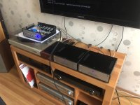
I totally forgot to share the conclusion of my original project here. As a resume, my pre-amplifier is totally build and works very well. In my modified design, I removed the tone and balance control totally. But I admit that with the volume control at the zero position, my Revox B760 tuner is a tiny tiny bit audible when this device is selected, but very low, almost imperceptible. I also suffer of the unbalanced image when the volume is at it's very beginning position. I will surely study more geoffw1 comment above!
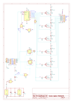
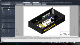
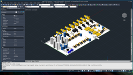
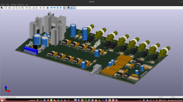
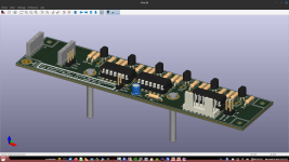
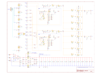
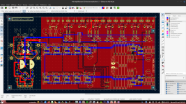
My design is made around selection of source inputs via relay, including a "TAPE MONITOR" input, named "MX1" for my other project "YB Multiplexeur MX1" ; a 4 to 1 R2R tapes or cassette decks multiplexer. All controlled digitally with the Adafruit soft touch module. I used KiCad 6.0 for the schematic drawings and the PCBs. I exported the PCBs as step file and imported them into the progeCAD software, an AutoCAD cousin, much much less expensive. From there, I draw the 3D model of the box based on the Modushop Sim Line 2U 230mm. But pictures is much better than words, so here is the full story...
Seeing that we are limited to 20 pictures, I included a DropBox link below to see all the 56 pictures, including books pictures that I read two times entirely!
https://www.dropbox.com/scl/fo/cimv...ey=8qk2sd1qvsn62ht0kf2z72wl6&st=y3zkhli5&dl=0
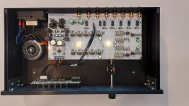
You will noticed an extra relay K7 at the AUX4 input, that cut also the ground connection of this input. This choice was made because my SONY television was always making a little noise even when not selected. I used this trick to totally disconnected it when not selected. I changed my SONY television for Samsung 65" Neo QLED recently and the problem is not present with this model. The relay can be replaced easilly with two wires shorting pins 4-5 and 8-9, if prefered.
I totally forgot to share the conclusion of my original project here. As a resume, my pre-amplifier is totally build and works very well. In my modified design, I removed the tone and balance control totally. But I admit that with the volume control at the zero position, my Revox B760 tuner is a tiny tiny bit audible when this device is selected, but very low, almost imperceptible. I also suffer of the unbalanced image when the volume is at it's very beginning position. I will surely study more geoffw1 comment above!
My design is made around selection of source inputs via relay, including a "TAPE MONITOR" input, named "MX1" for my other project "YB Multiplexeur MX1" ; a 4 to 1 R2R tapes or cassette decks multiplexer. All controlled digitally with the Adafruit soft touch module. I used KiCad 6.0 for the schematic drawings and the PCBs. I exported the PCBs as step file and imported them into the progeCAD software, an AutoCAD cousin, much much less expensive. From there, I draw the 3D model of the box based on the Modushop Sim Line 2U 230mm. But pictures is much better than words, so here is the full story...
Seeing that we are limited to 20 pictures, I included a DropBox link below to see all the 56 pictures, including books pictures that I read two times entirely!
https://www.dropbox.com/scl/fo/cimv...ey=8qk2sd1qvsn62ht0kf2z72wl6&st=y3zkhli5&dl=0
You will noticed an extra relay K7 at the AUX4 input, that cut also the ground connection of this input. This choice was made because my SONY television was always making a little noise even when not selected. I used this trick to totally disconnected it when not selected. I changed my SONY television for Samsung 65" Neo QLED recently and the problem is not present with this model. The relay can be replaced easilly with two wires shorting pins 4-5 and 8-9, if prefered.
Attachments
-
 04.png371.4 KB · Views: 41
 -
 23.png277.4 KB · Views: 34
 -
 31.jpg420.3 KB · Views: 38
 -
 38.jpg458.6 KB · Views: 36
 -
 51.jpg415.4 KB · Views: 35
 -
 52.png69.1 KB · Views: 35
 -
 54.png35.5 KB · Views: 36
 -
 55.png43 KB · Views: 30
 -
 56.png41.3 KB · Views: 39
 -
 22.png269 KB · Views: 33
 -
 15.png410.9 KB · Views: 33
 -
 14.png552.1 KB · Views: 29
 -
 05.jpg312.5 KB · Views: 33
 -
 07.png234.9 KB · Views: 31
 -
 08.png376.1 KB · Views: 33
 -
 09.png322.3 KB · Views: 39
 -
 10.png463.6 KB · Views: 36
 -
 11.jpg304.4 KB · Views: 36
 -
 12.png474 KB · Views: 31
 -
 13.png446.3 KB · Views: 35
Hi geoffw1:If you have a look through previous discussions relating to the original Self 2012, you will find that there was an issue that came up for some people that built it which related to irregularities with balance and ?noise? at low volume.
The volume control is an active design originated by Peter Baxandall and works by varying the negative feedback around an op-amp using a linear potentiometer. Dual linear pots are typically well matched for resistance potential ratios between the two channels but at extremes of rotational settings tiny difference in the potential ratios may cause audible differences between the left/right channel gains. Also the Baxandall circuit can never completely get to zero output (pretty close but not quite). As the gain of the Baxandall volume control is +16dB, reduction in this overall gain was a solution to the problem you are finding, especially as there's more than enough gain in the overall design than is needed to overload most power amps at full volume. If I remember correctly, if your build suffers from this problem, reducing the values of R25, R26, R27, R28 for one channel and R63, R64, R65, R66 from their current value of 3K3 to 1K resolves the issue.
On a separate note, as Jean-Paul said, K5, K6 are indeed line outputs taken prior to the balance and volume controls. In the original setup, these were intended as inputs to a level indicator circuit. Also, K7 is intended to go to a switch wired to operated the relay which can bypass the tone controls.
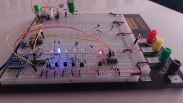
Following your advice, I replaced the 3k3 resistors with 1k. However, the problems did not improve. There is a sound that disturbs the ears at the lowest volume. The balance pot still does not work. Where could I be making a mistake.
Attachments
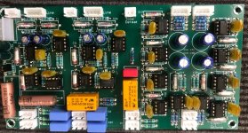
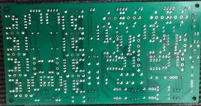
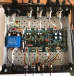
From the photos the pre-amplifier board appears to be very nicely soldered and does not appear to have any problems.
However, it appears that the terminal pitch of the four pots mounted on the panel does not match the pitch of the holes in the board, so the terminals have been widened and inserted. The pots may have a 2 mm pitch and the board 2.54 mm.

If excessive force is applied to the pot terminals, this may cause poor contact of the caulking part between the terminals and the resistive element.
Check if it is OK there.
However, it appears that the terminal pitch of the four pots mounted on the panel does not match the pitch of the holes in the board, so the terminals have been widened and inserted. The pots may have a 2 mm pitch and the board 2.54 mm.
If excessive force is applied to the pot terminals, this may cause poor contact of the caulking part between the terminals and the resistive element.
Check if it is OK there.
hi,
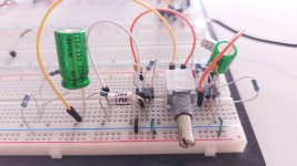
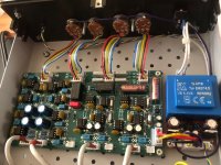
I solved one of the problems. I changed the pots. I combined the bodies of the pots with the circuit gnd. When I did this, the bad sound in the low sound disappeared. Only the balance setting does not work exactly. When I make it full right or full left, a little sound continues to come from the other channel. I hope I will fix this problem with your help.
I solved one of the problems. I changed the pots. I combined the bodies of the pots with the circuit gnd. When I did this, the bad sound in the low sound disappeared. Only the balance setting does not work exactly. When I make it full right or full left, a little sound continues to come from the other channel. I hope I will fix this problem with your help.
Attachments
I haven't checked it carefully yet, but looking at the circuit in Sevy's post #1...
I suspect that D. Self's balanced circuits are different from normal balanced circuits in that they are intended to be fine-tuned only, without completely reducing the volume when turned all the way to the right or all the way to the left.
If it is similar on the left and right sides, it may be normal (as D. Self designed it to be).
Hi mason_f8
Thank you for your help. Maybe this circuit works as you say. We can only learn the answer to this question from someone who has built and operated this circuit. When I turn the balance pot left and right, only the intensity of one of the channels decreases, but a little sound is still coming.
Thank you for your help. Maybe this circuit works as you say. We can only learn the answer to this question from someone who has built and operated this circuit. When I turn the balance pot left and right, only the intensity of one of the channels decreases, but a little sound is still coming.
If I ever make this preamp, will use a toroidal Transformer and keep it a away from pre board. Also will separate the relay ground from pre ground.
I haven't checked it carefully yet, but looking at the circuit in Sevy's post #1...
I suspect that D. Self's balanced circuits are different from normal balanced circuits in that they are intended to be fine-tuned only, without completely reducing the volume when turned all the way to the right or all the way to the left.
If it is similar on the left and right sides, it may be normal (as D. Self designed it to be).
I built the full version of this preamp, i.e. including the phono stage and LLL system, and I am extremely happy with it. Along the years I have used a number of preamps, including high-end models, and this one is by far the best I have ever had.
Here is what D.Self says about the balance circuit : "The balance circuit is a balanced stage with variable gain over a limited range. The maximum gain is +3.7dB and the minimum gain is 6.1dB. When the balance is set to center, the gain is 0.2dB."
I confirm that when the balance potentiometer is turned fully left or right the opposite channel is NOT mute, and I can live with this since I never felt the need to mute completely a channel. After all a balance pot is there only to to correct a slight imbalance between channels. A loud difference is the sign for a defect somewhere else in the audio chain.
I stand myself corrected, of course you should read "The maximum gain is +3.7dB and the minimum gain is -6.1dB"
Sorry for mistyping.
Sorry for mistyping.
Hi, Thmartin, it was good to get confirmation from a real user.
I then calculated the gain of this circuit
G = ((R8//R9)/R7)*(P1A+R13)/R13
I confirmed that the gain of this circuit is. (but with R7 = R10, R8 = R11 and R9 = R12)

If P1A is 1kΩ (max)
G = (500/1000)*(1470/470)=1.564=3.88dB
If P1A is 500 Ω (centre)
G = (500/1000)*(970/470)=1.032=0.273dB
When P1A is 0 Ω (min)
G = (500/1000)*(470/470)=0.5=-6.02dB
The value of Self is slightly lower, but this is probably due to the inclusion of the residual resistance of the pots in the circuit and the losses in the circuit.
I then calculated the gain of this circuit
G = ((R8//R9)/R7)*(P1A+R13)/R13
I confirmed that the gain of this circuit is. (but with R7 = R10, R8 = R11 and R9 = R12)
If P1A is 1kΩ (max)
G = (500/1000)*(1470/470)=1.564=3.88dB
If P1A is 500 Ω (centre)
G = (500/1000)*(970/470)=1.032=0.273dB
When P1A is 0 Ω (min)
G = (500/1000)*(470/470)=0.5=-6.02dB
The value of Self is slightly lower, but this is probably due to the inclusion of the residual resistance of the pots in the circuit and the losses in the circuit.
- Home
- Source & Line
- Analog Line Level
- Elektor Preamplifier 2012 new personnal project