Newbie here.
Almost finished with the PCB, and realized I was using 100 k resistors with 5 % tolerance rather than pack with 1 % tolerance which is what their color code indicates.
I think there are 17 in the first step I would have to do over 😱
😱
Does it matter? Should I start over or resolder?
Almost finished with the PCB, and realized I was using 100 k resistors with 5 % tolerance rather than pack with 1 % tolerance which is what their color code indicates.
I think there are 17 in the first step I would have to do over
😱Does it matter? Should I start over or resolder?
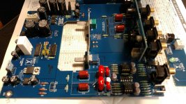
...Also, the push switch for mc/m has multiple pins in close quarters and there may be a solder bridge between 2 pins. Is that a problem? Are any of these parts with multiple close pins effected by solder bridges?
Thanks in advance
Thanks in advance
Solder bridges are never good. Clean them up.
As for 5% vs 1% resistors it’s not going to make any substantial difference at all. But as Victor mentions, your question is a bit unclear...
As for 5% vs 1% resistors it’s not going to make any substantial difference at all. But as Victor mentions, your question is a bit unclear...
there may be a solder bridge between 2 pins. Is that a problem?
Are any of these parts with multiple close pins effected by solder bridges?
You must remove any shorts, try solder-wick.
Thanks for the reply.
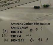
The%5 are already soldered in. Apparently the kit came with a duplicate set of 1% resistors in an unlabelled bag. I am done with the construction and have these 50 -100 extra resistors that are actually the ones indicated by the direction,s color code for 1%.
The solder bridges are across pins on the same component. Can you hear this in SQ or is it a potential problem down the road. Why does a component have multiple pins? Just trying to learn a little.
Thanks
Solder bridges are shortcuts. Shortcuts can create disastrous problems including fire. Do NOT connect the unit to the mains until you are confident that there are no solder bridges.
If the component has multiple pins then these are not supposed to be connected, otherwise the component would have less pins.
All active components have multiple pins as you control the current flowing through with another voltage or current at the input.
Also, unless you ordered the kit with a resistor upgrade, you should not have duplicate set of components. Did you actually measure the resistance?
I wicked away as much as I could and could not see a bridge with the naked eye, however I did not put a magnifying glass on it. Quite a bit of solder artifact/mess there.
BTW, this spot was on the phono switch so it would stand to reason that I should use this line at my own risk. The other parts with multiple pins we're scary close but did not appear to bridge.
I probably should have used a smaller solder tip?
The preamp seems to work ok , hooked up to the ACA 1.6 - thanks 6L6! It's you fault I am thoroughly hooked albeit ignorant as hell🙂
No hum, equal channels, very clean sounding with no coloration. A fun build. Good directions, but just not quite up to the level of handholding as the1.6 has.
Attached is the bag that had the 5 % resistors, naturally gravitate towards that as it was the only one labelled. I did measure some resistors and googled color codes , but was not aware of the tolerance variability, incidentally not numerically printed in directions. Would you measure each of 150 resistors? And why, just to see if there is a bad one? I read colors just fine - honest question
Thanks again for tips advice input etc
You do not need to measure all resistors, just one from each group with the same color code in order to make sure you did not read the codes from the opposite direction and did not consider orange to be brown etc.
- Status
- Not open for further replies.