Hi Guys,
I picked up a guitar from a local second hand website a week ago. The guy gave me a free amp that doens't work to play with. I like tech and am into IT, but electronics is somewhat new to me. The amp I got is a Fender Stage Lead. I love the looks, I love the sound (it works sometimes, ill get to that and why)
After a lot of measuring and resoldering one faulty connector on channel 1 I am at the point where i have to ask for some advice since I dont know if this decision will fry me or not.
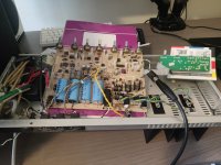
When I place the PCB board on a piece of something that is non conductive, everything about the amp works. Channel 1, channel 2, gain, reverb, everything. However, when I actually screw the board into the main metal chassis, it works occasionally and I have to wiggle the potentiometers around to get it to work. One note: when it is not connected to the chassis at all. Sometimes the amp stops working. In that case, when I plug my JBL speaker with cable into preamp out i hear a pop, and it starts working again.
Here's the thing. The metal chassis frame has a ground cable coming from it. What I THINK is happening is that there are 3 cases.
1. Nothing is grounded via the metal chassis, and thus, the circuit seems to work.
2. All the potentiometers are connected to the chassis and are all grounded. Thus, the circuit works.
3. Somewhere in the middle, some potentiometers are grounded and some are not. Resulting in circuit not working?
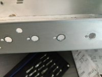
Between the potentiometer and metal chassis there are so called "star washers". Im making sure the screws on the other side are real real tight, hoping for contact. But to no avail. I screw the board into the chassis, sometimes it works, sometimes it doesn't. Sometimes for 10 minutes, sometimes it doenst work anymore at all.
I made sure to test them screwed in by measuring with continuity on my multimeter whether the potentiometers have continuity with the chassis, they all do. Even then, the signal doesnt work sometimes and sometimes it does.
My thoughts:
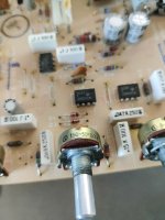
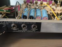
Either, solder a wire from every potentiometer to a connector. And connect the other side of the connector to the common ground in the chassis as you can see in one of the photos.
Option two: add rubber washers between all the potentiometers instead of the star washers. But will this fry me? Is it required for the potentiometers to be grounded? I added a picture of everything i think could be usefull. The potentiometers, the star washers, the electrical circuit so you can see the ground, the common ground. I hope someone can help me, i'd love to get this thing playing agian.
I picked up a guitar from a local second hand website a week ago. The guy gave me a free amp that doens't work to play with. I like tech and am into IT, but electronics is somewhat new to me. The amp I got is a Fender Stage Lead. I love the looks, I love the sound (it works sometimes, ill get to that and why)
After a lot of measuring and resoldering one faulty connector on channel 1 I am at the point where i have to ask for some advice since I dont know if this decision will fry me or not.
When I place the PCB board on a piece of something that is non conductive, everything about the amp works. Channel 1, channel 2, gain, reverb, everything. However, when I actually screw the board into the main metal chassis, it works occasionally and I have to wiggle the potentiometers around to get it to work. One note: when it is not connected to the chassis at all. Sometimes the amp stops working. In that case, when I plug my JBL speaker with cable into preamp out i hear a pop, and it starts working again.
Here's the thing. The metal chassis frame has a ground cable coming from it. What I THINK is happening is that there are 3 cases.
1. Nothing is grounded via the metal chassis, and thus, the circuit seems to work.
2. All the potentiometers are connected to the chassis and are all grounded. Thus, the circuit works.
3. Somewhere in the middle, some potentiometers are grounded and some are not. Resulting in circuit not working?
Between the potentiometer and metal chassis there are so called "star washers". Im making sure the screws on the other side are real real tight, hoping for contact. But to no avail. I screw the board into the chassis, sometimes it works, sometimes it doesn't. Sometimes for 10 minutes, sometimes it doenst work anymore at all.
I made sure to test them screwed in by measuring with continuity on my multimeter whether the potentiometers have continuity with the chassis, they all do. Even then, the signal doesnt work sometimes and sometimes it does.
My thoughts:
Either, solder a wire from every potentiometer to a connector. And connect the other side of the connector to the common ground in the chassis as you can see in one of the photos.
Option two: add rubber washers between all the potentiometers instead of the star washers. But will this fry me? Is it required for the potentiometers to be grounded? I added a picture of everything i think could be usefull. The potentiometers, the star washers, the electrical circuit so you can see the ground, the common ground. I hope someone can help me, i'd love to get this thing playing agian.
Attachments
-
 IMG_20250602_203929.jpg301.2 KB · Views: 114
 -
 IMG_20250602_203945.jpg303.6 KB · Views: 107
 -
 IMG_20250602_203951.jpg288.9 KB · Views: 107
 -
 IMG_20250602_204003.jpg187.9 KB · Views: 104
 -
 IMG_20250602_205548.jpg419.2 KB · Views: 115
 -
 IMG_20250602_204045.jpg859.2 KB · Views: 120
 -
 IMG_20250602_204009.jpg320.6 KB · Views: 119
 -
 IMG_20250602_205554.jpg329.3 KB · Views: 113
 -
 IMG_20250603_202257.jpg452.1 KB · Views: 119
 -
 IMG_20250603_202300.jpg344.4 KB · Views: 111
Last edited by a moderator:
Do you have a complete schematic for this amplifier (what is the model number and serial number)?
Do you have a DVM//multimeter?
Do you have an oscilloscope? (even a soundcard oscilloscope might be workable in this case.)
Do you have any kind of signal generator, even such as an audio dac in your computer?
BTW, if any of the potentiometers short out to ground when attached to the metal chassis, then the potentiometer is bad and should be replaced. Using rubber insulators as a bandaid would not be an appropriate solution.
Last edited:
 Moved to Instruments & Amps per forum policy.
 Good luck, hopefully lots of help to help you get this fixed.
Presumably the amp worked as it is from the factory. So I don’t think adding a new grounding setup will work.
It’s more likely that you have cold solder joints on the PCB that are flexed in and out of position.
Get a magnifying glass and check all the joints for the potentiometers. Then check all the other joints too. You’re looking for cracks or little lines. You can also just reflow all the joints if you don’t want to spend time diagnosing it.
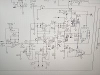
@Markw4 I do have a schematic: https://el34world.com/charts/Schematics/Files/Fender/Fender_stage_lead.pdf
The model is the Fender Stage Lead.
I do have a multimeter. I sadly do not have an oscilloscope. I have a Raspberry PI with a dac with rca that i use to play music on my other amp. But normally i just use my guitar for signal in.
When screwing the potentiometers to the chassis i use the multimeter to make sure they all have continuity with it. Why should the potentiometer actually be grounded? They work without being grounded and the board itself should be grounded through the connector to the wall right?
Also, if the potentiometers are connected to the chassis and therefore grounded, and I plug the amp in a wall socket that is not grounded. It shouls still work right?
@ahankinson
I also checked out all of the potentiometer and did a reflow of each of the solder joints. I don't think that is the problem. I can really tell that as soon as the board partly touches the chassis, the signal dies.
Thanks for the rapid reply guys. I hope you have more advice for me 🙂
Okay. Visual inspection of the board with the power off is usually the first thing to do.
If nothing turns up, then electrical testing with power on can be done. A common technique would be to introduce a test signal into the guitar input then follow it thought the amplifier circuitry until you find a point where the signal is lost. Then change the focus of the troubleshooting to that local part of the circuit.
A signal source such as a signal generator playing a test tone, or even some music fed into the amplifier input can work. The test signal can be followed or traced through the circuitry using an oscilloscope, a signal tracer (basically an audio amplifier with a protected input), or with an AC voltmeter.
In this case the guitar amp circuit is divided into two main sections, the preamp section, and the power amp section. There are jacks where signals can be injected or traced already available. You could try putting a test signal into the guitar input, then check for the signal at the preamp output jack. You can also inject a test signal into the power amp section to see if its still working when the pots are tightened down.
Also, there are two channels in the preamp section, so you need to check if only one of the channels is failing or if they both are. Also you can try moving all the controls around when the problem is present to see if moving the controls has any effect on the symptom.
If none of that stuff helps find the problem, then we would need to look at the schematic and figure out how the guitar signal passes through the various areas of circuitry so we can trace where the guitar or test signal is getting lost. If it gets to that point I will mark up the schematic for you to indicate signal flow paths.
Something else to maybe consider, there are very cheap oscilloscopes that can be used for simple low voltage audio circuit troubleshooting. Prices start at under $30. Of course, its nice to have one with two channels and that comes with probes. https://www.ebay.com/sch/i.html?_nk...sacat=0&_from=R40&_trksid=p2332490.m570.l1313 ...used scopes may be a good option too. Of course, once you get one then you would need to learn how to use it.
Last edited:
All user-touchable parts need to be grounded for safety. This is to ensure that any loose connections to the mains immediately trip a breaker or blow a fuse so that the chassis is not energized with potentially lethal voltages. You do not want to operate an amplifier that is not grounded. If your amplifier does not have a three-prong plug, or that three-prong plug is not connected to the chassis, it is dangerous. (Look up how Keith Relf died, for example: https://elvispelvis.com/keith-relf-age-32-cause-of-death-electrocuted/). If you have a guitar in your hands that is connected to an unearthed connection, and your lips touch a microphone to a PA that is earthed, and your chassis is (unknowingly) live, then your arms, heart, and face become the path to ground. Not good.
Functionally, many potentiometers route the signal to ground. When you turn a volume knob, for example, you're likely adjusting the balance between how much of the signal is being sent to ground, and how much is sent through the rest of the circuit. (It's more complicated than that, but that's the basic explanation).
Both of those suggest a loose connection somewhere. When you wiggle the potentiometers, it's flexing some joint causing an intermittent connection. It might be a faulty jack too, that plugging your speaker in / out causes to work. It could also be that some loose connection or shoddy rework (has this been "repaired" before?) is causing a short to ground.
Maybe take some high-res photos of the bottom of the PCB and post them?
Either way, it's sounding to me like a mechanical fault rather than an electrical one. Try getting a non-conductive probe (like a wooden chopstick) and poking the board and the components to see if you can get it to reproduce the intermittent fault reliably.
The suggestion about checking both channels is a good one. You're basically trying to work backwards from the signal input.
Functionally, many potentiometers route the signal to ground. When you turn a volume knob, for example, you're likely adjusting the balance between how much of the signal is being sent to ground, and how much is sent through the rest of the circuit. (It's more complicated than that, but that's the basic explanation).
In that case, when I plug my JBL speaker with cable into preamp out i hear a pop, and it starts working again.
However, when I actually screw the board into the main metal chassis, it works occasionally and I have to wiggle the potentiometers around to get it to work.
Both of those suggest a loose connection somewhere. When you wiggle the potentiometers, it's flexing some joint causing an intermittent connection. It might be a faulty jack too, that plugging your speaker in / out causes to work. It could also be that some loose connection or shoddy rework (has this been "repaired" before?) is causing a short to ground.
Maybe take some high-res photos of the bottom of the PCB and post them?
Either way, it's sounding to me like a mechanical fault rather than an electrical one. Try getting a non-conductive probe (like a wooden chopstick) and poking the board and the components to see if you can get it to reproduce the intermittent fault reliably.
The suggestion about checking both channels is a good one. You're basically trying to work backwards from the signal input.
@ahankinson . I get your point. I agree this stuff should be grounded properly. I placed an extension cord to another room that has a grounded wall outlet and will continue to debug with the board screwed in the chassis and thus grounded.
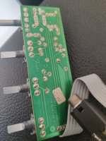
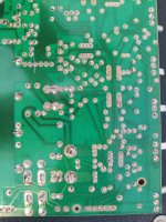
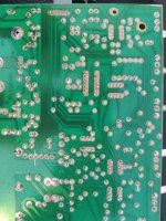
I attached pictures of the back of the board. I already reflowed the pots. There was a loose connection to the channel 1 board which is separate. But i resoldered it. Now, it ALWAYS works when channel 2 also works. Im very certain the problem is not in channel 1.
If it is actually a mechanical problem, shouldnt the board not work at all? It works kind well untill (part of) the board connects to the chassis and becomes grounded. Thats when the issues arrise.
Attachments
If channels 1 & 2 both work or both don't work, then the remaining problem must be later in the signal flow. Please check at the preamp output jack.
I would guess that a twisted pair of wires has the wires reversed at one end (by the previous owner).
Well, by mechanical I mean that it’s not a failed electrical component (like a capacitor or transistor) but more likely a physical switch or loose wire or something. I’m not saying it isn’t electrical, I’m just saying that the symptoms would lead me to believe it’s worth ruling out the mechanical causes first before changing any wiring.
We also have to assume that it worked when it left the factory, so the main question is “what changed?” It’s unlikely that Fender got their grounding wrong on this particular amp. So something either failed due to wear or a botched repair changed something. An intermittent fault could be something as simple as a dirty connector or an internal switch in one of the jacks that has failed.
(I don’t know about this amp specifically, but many have a switch in their jacks to make or break a connection when a plug is inserted, and it’s not uncommon for those to fail).
Okay, @ahankinson @Markw4 I think i have a breakthrough. I put everything back together. Turned on the amp and checked the pots and inputs for grounding in a grounded socket. They all showed continuity with the chassis. So my initial thought that the grounding of the pots was the issue is not true.
Next i put my laptop on the guitar input and started playing music. It started playin on the amp and then i smacked the amp a bit softly, and the music stopped. I got a chopstick and started poking. After some time i found that, if i try to bend the board upwards a bot on backside of the amp, the music starts playing again. I feel there are 2 options.
1. There is a connection that is cracked and for some reason, lifting the board fixes it.
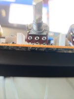
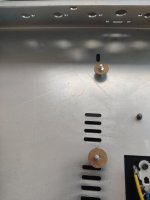
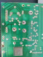
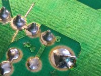
2. There is a stand off (i think) at the back of the board. I attached the picture to this reply. Which I think may contact the bottom of the chassis. It is very close to the location where i specifically have to lift the board. I also added a video so you can see.
The board is bolted with 4 screws to the chassis. The only other location where it touches the chassis is through the pots, but that is still the case when I lift the board. In Addition, the 4 screws have non conductive stuff inbetween them and the board.
What are your thoughts?
I willl try tomorrow to slip a piece of non conductive rubber under the standoff, because i dont think the standoff is conductive nor a ground connection to the chassis.
Next i put my laptop on the guitar input and started playing music. It started playin on the amp and then i smacked the amp a bit softly, and the music stopped. I got a chopstick and started poking. After some time i found that, if i try to bend the board upwards a bot on backside of the amp, the music starts playing again. I feel there are 2 options.
1. There is a connection that is cracked and for some reason, lifting the board fixes it.
2. There is a stand off (i think) at the back of the board. I attached the picture to this reply. Which I think may contact the bottom of the chassis. It is very close to the location where i specifically have to lift the board. I also added a video so you can see.
The board is bolted with 4 screws to the chassis. The only other location where it touches the chassis is through the pots, but that is still the case when I lift the board. In Addition, the 4 screws have non conductive stuff inbetween them and the board.
What are your thoughts?
I willl try tomorrow to slip a piece of non conductive rubber under the standoff, because i dont think the standoff is conductive nor a ground connection to the chassis.
Attachments

You could put your multimeter across the points from a known ground (like the case of a pot) to the point where you think it’s shorting (with the power off). Check it in both conditions. If it’s not supposed to be shorting and it is, then you have your problem.
My money is still on a cracked joint, though. Those transistors have heat sinks so they must see a bit of heat. You might try reflowing the solder on them and any other component around there.
My money is still on a cracked joint, though. Those transistors have heat sinks so they must see a bit of heat. You might try reflowing the solder on them and any other component around there.
The piece of the board i have to bend upwards is quite far from the transistors. Maybe its somewhere around the caps? Im gonna see if i find something after unscrewing the board @ahankinson
At first I would resolder all potentiomer joints.
These are the most propable failures.
Not always a cracket joint is visible.
And if that does not solve the problem,
bend each potentsiometer to find the culprit.
Sometimes a solder pad of a potentiometer is broken,
thus the pcb trace must be patched.
These pcb soldered pots are a pain in the a**
These are the most propable failures.
Not always a cracket joint is visible.
And if that does not solve the problem,
bend each potentsiometer to find the culprit.
Sometimes a solder pad of a potentiometer is broken,
thus the pcb trace must be patched.
These pcb soldered pots are a pain in the a**
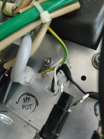
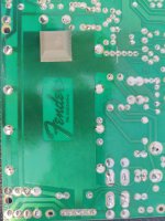
@ahankinson @Markw4 and others i would like to update you. I started poking around with a chopstick and found the issue. It was one of the connectors. I drew it on the attached images. I resoldered and amp is as new now. Loving the sound of the clean channel. Thanks for your help guys!
Attachments

- Home
- Live Sound
- Instruments and Amps
- Electronics noob eager to learn asking for help on a Fender Stage Lead amp that I think has grounding problems