So I've decided to make nice big beefy 1950's replica of Nixie clock inspired by old HP gear. I will use XO for start and later 10Mhz OCXO.
First designing relays for that authentic clicking sound of old gear, 45 relays all together 1 relay for each digit. relays connecting tube cathodes to the ground.


First testing of tubes, in my project I'm using IN-1 Soviet tubes and DC step up 180V

First designing relays for that authentic clicking sound of old gear, 45 relays all together 1 relay for each digit. relays connecting tube cathodes to the ground.
First testing of tubes, in my project I'm using IN-1 Soviet tubes and DC step up 180V

Fan cooled clock---huh? 🙂
Here's another timely project that might interest you!
diytube.com • View topic - Vacuum Tube Time Machine
Here's another timely project that might interest you!
diytube.com • View topic - Vacuum Tube Time Machine
Wow wicked thank you very much for link. One of my future projects is pure relay nixie clock and of course simple version of nixie clock.
Sent from my Nexus 5 using Tapatalk
Sent from my Nexus 5 using Tapatalk
Tubes soviet IN-1 nixies with 3D printed unobtanium sockets. I used Molex connectors for pins. This is 11 pin tube. 1 Anode, 10 Cathodes (0-9)

Fist testing done, of course nothing was working, but after a little bit of debugging all works, ribbon cables used.

Detail of 0.1" PCB connector. I'm using 15k dropp off resistor for anode to prolog life of tubes. Also tubes are on-off switchable and dim-bright function on front panel.

This a real high tech wooden block 🙂 Tubes are running, although inputs of relay are manually controlled by 5V for now. 5V via 1K resistor and 2N222 NPN transistor openning ground of relay


Of course I would make my own PCB, instead of using prototyping PCB's but that's learning progress. Also these cheap paper pressed PCB's don't look the deal either 🙂
Fist testing done, of course nothing was working, but after a little bit of debugging all works, ribbon cables used.
Detail of 0.1" PCB connector. I'm using 15k dropp off resistor for anode to prolog life of tubes. Also tubes are on-off switchable and dim-bright function on front panel.
This a real high tech wooden block 🙂 Tubes are running, although inputs of relay are manually controlled by 5V for now. 5V via 1K resistor and 2N222 NPN transistor openning ground of relay
Of course I would make my own PCB, instead of using prototyping PCB's but that's learning progress. Also these cheap paper pressed PCB's don't look the deal either 🙂
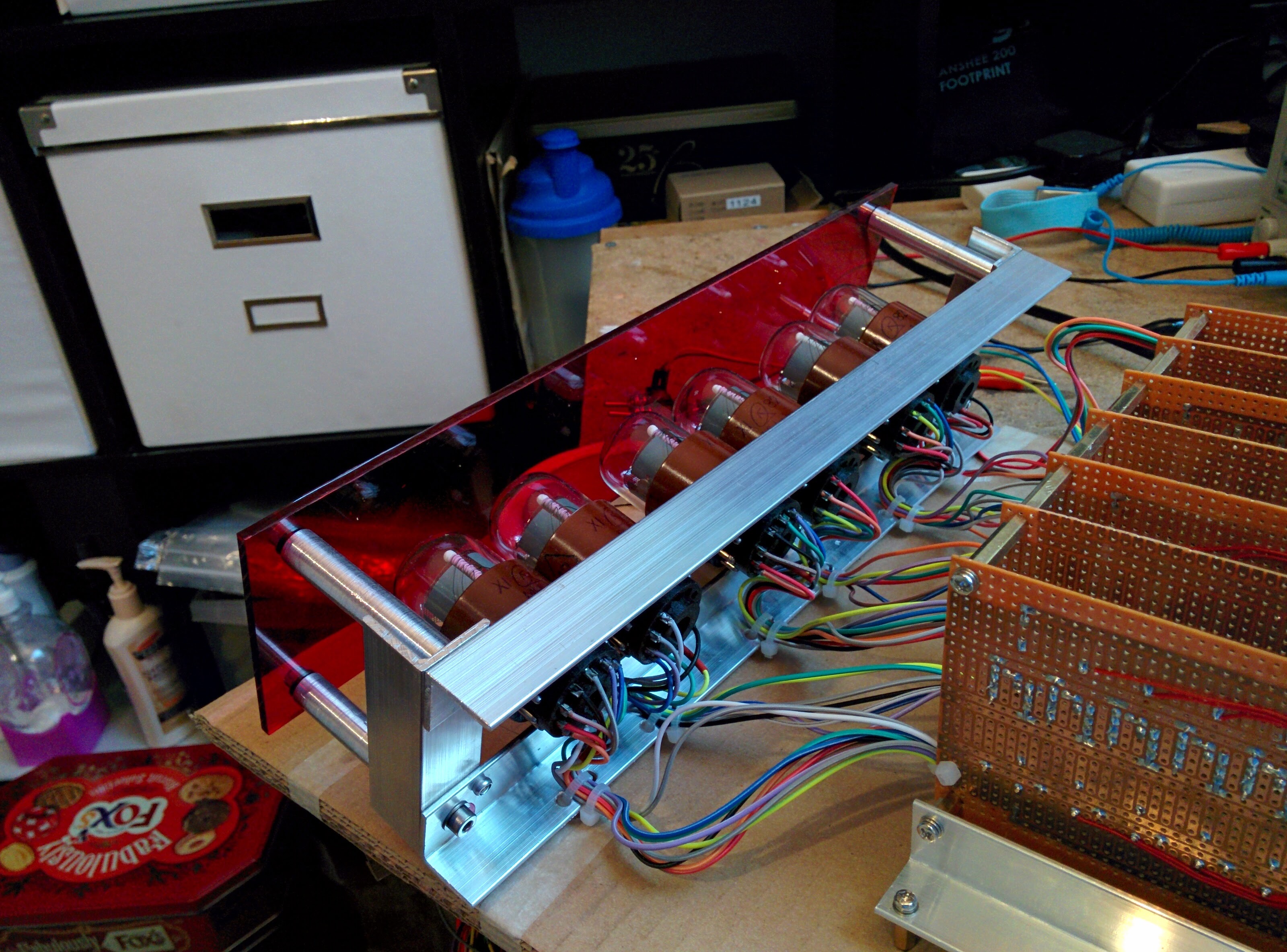
Testing Display and red Perspex display cover 4401 RED, 3mm, A4 (297mm x 210mm) used
Digits are set manually.


Digits are set manually.
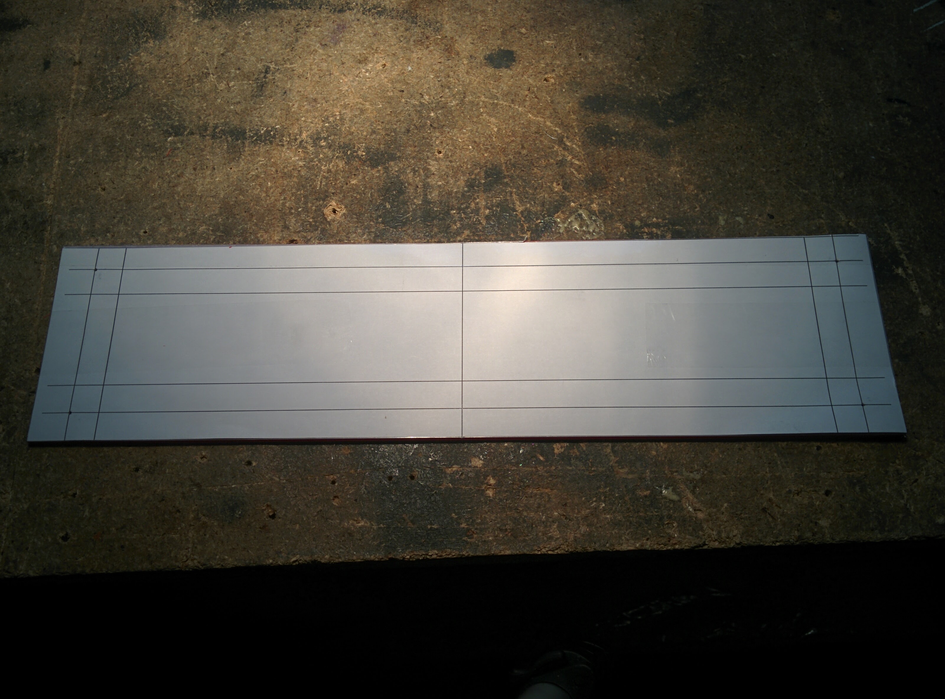
First idea / drawing of front panel & button / switch placement.
Front panel is Aluminium 4mm CNC machined gray powder coated with engraving and black infill. Handles chrome plated Hammond 7" steel rack handles.
Rear and bottom 2mm brushed aluminium
Top / sides 1.2mm Aluminium black hammered paint

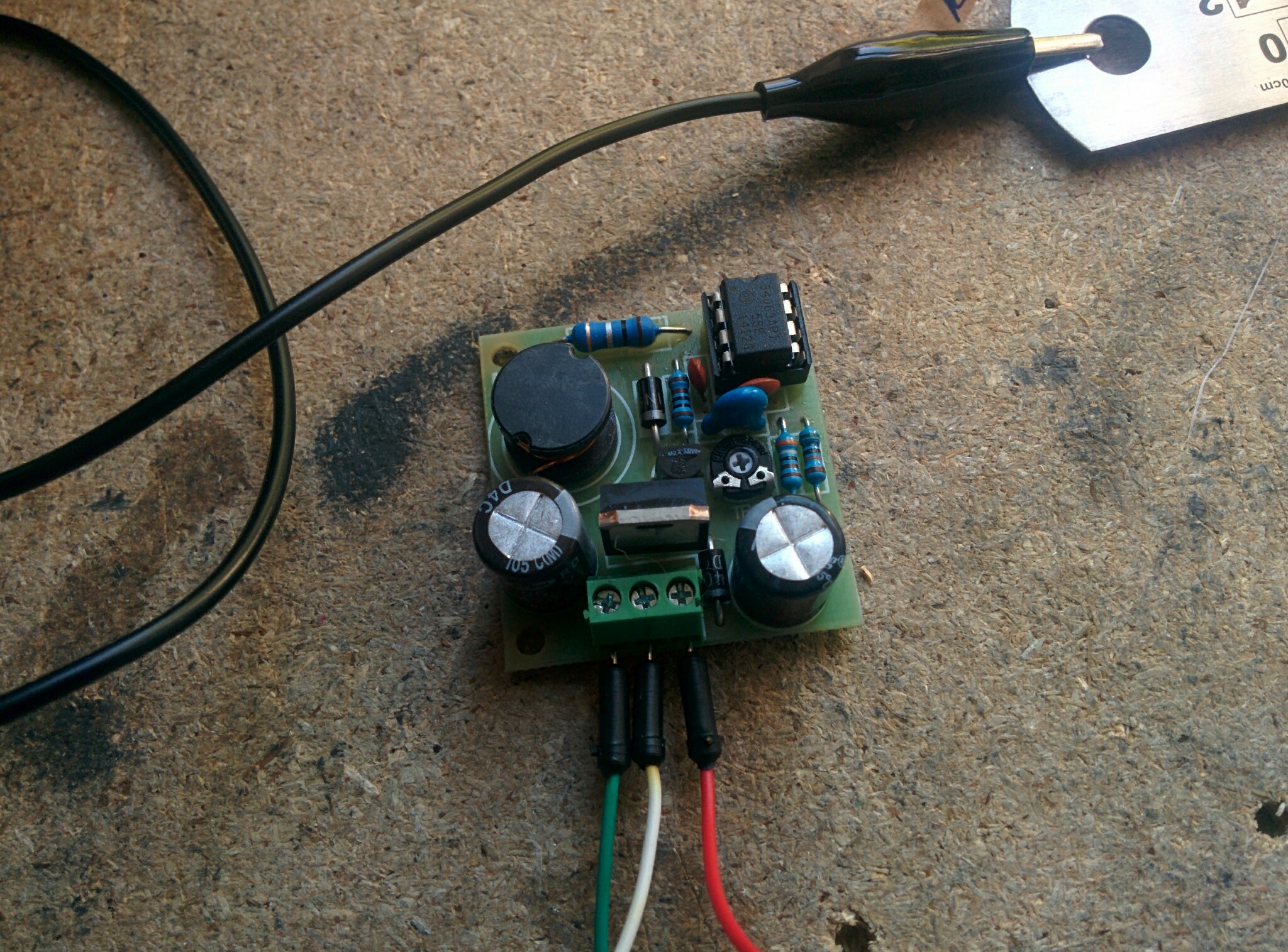
Prototyping / testing my idea of Transient display switch on for 20 seconds. Used 555 timer. Relay switching 180V PSU for nixie tubes.

Now board is done (just lettering missing)
Functionality:
- display on / off with SPST switch
- 20s transient display ON with push button
- dimming display with SPST switch. Every Tube anode with 15k drop resistor, Dimming achieved with with pair of 7.2k resistors, bypassed by SPST switch for full brightness. This is lowest value I could get before digits were still able to display in full shape.

Now testing in circuit. still long way to go.

This clock is basically tribute / inspired by HP model 571B mechanical clock and late 50, early 60 HP frequency meters, generators and other gear


Front panel is Aluminium 4mm CNC machined gray powder coated with engraving and black infill. Handles chrome plated Hammond 7" steel rack handles.
Rear and bottom 2mm brushed aluminium
Top / sides 1.2mm Aluminium black hammered paint
Prototyping / testing my idea of Transient display switch on for 20 seconds. Used 555 timer. Relay switching 180V PSU for nixie tubes.
Now board is done (just lettering missing)
Functionality:
- display on / off with SPST switch
- 20s transient display ON with push button
- dimming display with SPST switch. Every Tube anode with 15k drop resistor, Dimming achieved with with pair of 7.2k resistors, bypassed by SPST switch for full brightness. This is lowest value I could get before digits were still able to display in full shape.
Now testing in circuit. still long way to go.
This clock is basically tribute / inspired by HP model 571B mechanical clock and late 50, early 60 HP frequency meters, generators and other gear
Some metalwork:
Display holder with red plexi. made of 20x20 aluminium L shape, posts for plexy turned on drill 🙂
Main problem was to find out an angle of tube sockets as these tubes were not manufactured with precision, like some later models.


Making tube display assembly:
After assembly of L shape aluminium profiles I attached 10 x 60 mm posts with M4 threaded holes. Cut A4 perspex to size by Stanley knife from both sides and snapped. This creates nice accurate edge. Then use puncher and drill 2, 3, 4 mm to drill hole of desired size. Persex is much easy to work with then I thought.


Display holder with red plexi. made of 20x20 aluminium L shape, posts for plexy turned on drill 🙂
Main problem was to find out an angle of tube sockets as these tubes were not manufactured with precision, like some later models.
Making tube display assembly:
After assembly of L shape aluminium profiles I attached 10 x 60 mm posts with M4 threaded holes. Cut A4 perspex to size by Stanley knife from both sides and snapped. This creates nice accurate edge. Then use puncher and drill 2, 3, 4 mm to drill hole of desired size. Persex is much easy to work with then I thought.
- Status
- Not open for further replies.
- Home
- General Interest
- Everything Else
- Electromechanical Relay Nixie tube clock 1950's cold war replica