So I have a headphone amp that I just purchased, is based on a JC-2.
It has a conventional zobel and just downstream there is a 47uf cap in series with a 5k R to ground.
Would this be there to provide a slight load, for stability, or ?
It has a conventional zobel and just downstream there is a 47uf cap in series with a 5k R to ground.
Would this be there to provide a slight load, for stability, or ?
Attachments
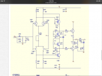
...47uf cap in series with a 5k R to ground....
Looks like 1.2K.
You did not mention the 10K.
Output is clearly from L_OUT.
LV- is something else. Not Shown. My *guess* is DC error detection with large audio signals suppressed 10:1.
If that is the function, the cap should be non-polar. Polar electrolytic may work for some time, but "is wrong" when the voltage may be reversed for extended time.
I presume "based on" is a loose description.
Thanks, the board does have a 1237 protection circuit/relay, so that would be where that leads to.
I have a better understanding of this now, thanks again.
I will replace the electrolytic with a bipolar part as well.
Amp sounds great though!
I have a better understanding of this now, thanks again.
I will replace the electrolytic with a bipolar part as well.
Amp sounds great though!
Oh wow, I didn’t see the reference showing that.
Now I will have to add a bypass on that one too...
Now I will have to add a bypass on that one too...
Oh wow, I didn’t see the reference showing that.
Now I will have to add a bypass on that one too...
What?
So I have a headphone amp that I just purchased, is based on a JC-2.
It has a conventional zobel and just downstream there is a 47uf cap in series with a 5k R to ground.
Would this be there to provide a slight load, for stability, or ?
Looks like bass boost to me. High frequencies get attenuated some, low frequencies less.
BTW Those caps valued '104' and '473' of course are 100nF and 47nF respectively ;-)
Jan
Last edited:
I have put a 10nf bypass on the 47uf electrolytic feedback capacitor, and am using some Russian polystyrene parts for the rest of the smaller sizes.
The board uses, and is labeled 100nf in the locations that are indicated as 47nf on the schematic. I am using 47nf in both positions, since I have a decent quantity here.
There is a reference to “LV -“ that tells the complete story, is the feedback loop, and that was pointed out earlier. There is another “LV-“ callout elsewhere on the schematic.
At first glance the circuit can look different if you don’t take that into consideration, and I was also thinking it could be some bass boost type of filter until it was made apparent.
I really shouldn’t work on this stuff when I have the flu...
Sounds very good now.
Maybe they had to go to lunch and forgot to draw in that last leg or something? Who knows...
Now I just need to let it run for a long while and get some rest.
Now I just need to let it run for a long while and get some rest.
Could they have drawn that schematic a little worse?
I know I could. But that's me.
Why? Do you like the sound of a slight HF suckout (where the 10nF capacitance resonates with the 47uF inductance)?phase said:I have put a 10nf bypass on the 47uf electrolytic feedback capacitor
- Status
- Not open for further replies.
- Home
- Amplifiers
- Headphone Systems
- Electrolytic parallel to load