What's the polarity of an electrolytic cap as output coupling:
-Positive output
-Negative output
I think is positive output is OK?
-Positive output
-Negative output
I think is positive output is OK?
It depends on the circuit,but usually the (-) side would be the output.
For example,a cap coupled power amplifier output,the speaker is basically just a short-circuit to ground at DC. And the output node (before the cap) of the amplifier would be at about 1/2 Vcc.
The (-) goes to the 'most negative' side. 🙂
(EDIT: This all assumes that the supply voltage is a POSITIVE value above ground. )
Last edited:
Yes, but if chosen carefully it can also prevent unwanted subsonics from getting though too.
So positive is the output, ok?
I have a load of only 300 ohms so I need a capacitor value of 265uF so I will use 220uF 50V Pana FM that I have on hand.
Thank to remind, I used the V-cap coupling capacitor calculator. http://www.v-cap.com/coupling-capacitor-calculator.php
Last edited:
Right. What you want to know is if the amplifier's DC output is positive compared to ground. If it is, then the positive terminal of the output cap goes to the amp, the negative to the speaker or headphone.
Pretty simple, connect the positive terminal to the side that has a positive voltage compared to where the other side goes. You can check that with a volt meter.
Pretty simple, connect the positive terminal to the side that has a positive voltage compared to where the other side goes. You can check that with a volt meter.
Merlin, please post the circuit schematic. I think most of the earlier posts have assumed that you have a single power rail (e.g. amplifier operating between +24V and ground) in which case it is easy to see which way to orient the capacitor.
If you have two rails (e.g. +12V and -12V), the output is probably near ground anyway and it *might* not matter which way the capacitor is connected. If the circuit is built except for this capacitor, measure as suggested by Pano.
If you have two rails (e.g. +12V and -12V), the output is probably near ground anyway and it *might* not matter which way the capacitor is connected. If the circuit is built except for this capacitor, measure as suggested by Pano.
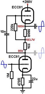
Thanks for the schema. Definitely put the + pole to the Cathode. Use a cap with the proper voltage rating.
I have to say, I would not be crazy about putting headphones on my cranium that have only a cap between me and 185V DC.
I have to say, I would not be crazy about putting headphones on my cranium that have only a cap between me and 185V DC.
Thanks Pano, other way to avoid DC will be a transformer but wich one having in mind that I'm still looking for a headphone amp so I don't know the primary value only the knwon value is that I need a secondary with 300 ohms for my Senns, do you know a transformer with several primaries to match different output impedances?
Put a resistor across the headphones (1K?). This will avoid loud clicks when you plug them in, and reduce the risk of high voltage in case the phones go open circuit. Remember that all electrolytics leak a bit of current - this is how they work.
Sorry my ignorance, between positive & ground of each channel? 1/4W, 1/2W? If yes don't change the input impedance of the Senns?
Between signal and ground of each channel. There is no positive as music is AC. It will make the valve amp work a bit harder, but safety is worth paying for. 1/4W should be fine. All preamp/line stage/headphone outputs should have a ground reference resistor like this.
Thank you, good to know the use of a ground reference resistor. It's necessary also for a preamp?
Last edited:
safety is always relative, and can be layered - the headphone wiring, insulation is likely adequate as long as there are no failures - to be at risk of shock requires a fault in insulation system and coupling C happening together
still you could take the design challenge as making the headphone output "touch safe" for any single fault in the amp circuit
“the game” played by rating agency rules counts any active device, unrated insulation system to already have failed in worst case condition before applying “single fault” analysis to rated safety components
used within their ratings (after other worst case component failures) resistors may be assumed to fail open, diodes, TVS to fail shorted
safety grounded output transformer secondary with adequate pri-sec insulation construction is probably the simplest route
I don't believe any electrolytic C is recognized as safety rated insulation, some sufficiently high V rated flim or ceramic C may be - but the size and cost will be daunting for the required ~30 uF min - I'd like to see 100 uF for low phase shift bass - you need 2 2x sized C in series since "the game" requires assuming one fails shorted
assuming the (electrolytic or single non safety rated film) coupling C is a short for safety analysis you can make a sufficiently robust V clamp that passes the headphone drive V
~20 V rated bidirectional TVS to safety gnd, across the heaphone output terminals could work - may give some audio performance compromise due to the large, nonlinear C of the TVS - would require supply series R or fuse sized with TVS continuous power limit in mind
the few nF C of these TVS is large enough to give amp stability concerns as well - I don't know u-follower stability details off hand
more elaborate clamping can reduce C – bias 2 TVS/Zeners to +/- V > headphone drive Vpk (~12 V to drive HD600 to 120 dB)
then clamp with reverse biased rectifier diode pairs to these clamp rails – the rectifier diode’s C can be in the 10s of pF
possibly the biasing V could come from V multipliers running from the heater winding – only 10s of uA are required
the C leakage drain R could be >10 kOhms, not a loading issue
Last edited:
- Status
- Not open for further replies.
- Home
- Design & Build
- Parts
- Electrolytic cap as output coupling