Your drawing is close but not quite right. However, it is quite tricky to translate what's on the crossover board onto paper. You show the capacitors in parallel with each other, in which case they should be in series with the midrange. I may post my version later for your future reference.
It doesn't matter though, just replace each capacitor with another of the same value.
I have been encouraging you not to spend too much money on replacement capacitors, so please buy ones which are affordable to you.
It doesn't matter though, just replace each capacitor with another of the same value.
I have been encouraging you not to spend too much money on replacement capacitors, so please buy ones which are affordable to you.
also 1ft (30cm) cable of Konig OFC has 0.2-0.3ohms resistance while 0.5mm CSA (tin plated copper wire) inside Aiwa Exos 9 has above 1 ohm of resistance
You must be including the resistance of the leads and probes of your multimeter! Connect your multimeter leads together and note the ohms reading. Subtract that reading from any future resistance measurements.
30cm of 0.5mm diameter copper wire will have a resistance of only around 0.03 ohm - insignificant.
30cm of 0.4mm diameter copper wire will have a resistance of only around 0.05 ohm. - insignificant.
As I think I said earlier on in the thread, the resistance of the internal wiring in your unit is so low that it is not worth replacing it.
This is my place Transfer Multisort Elektronik - Electronic components to go when buying electronic components since they can be bought bulk and cheap, like resistors 50+ ( sometimes minimum quantity is 100 pieces, sometimes only 1) 2 cents per resistor, or capacitors, tried to look on ebay 10uF MKP capacitors in UK and it gave many results where people ask too much price like 12gbp with 1gbp shipping (or about 15-16usd) which is nonsence when those caps are not even something High End like Mundorf you mentioned before.Just sucks that anything you order from TME is 5gbp (7usd) shipping yet is still cheaper than paying 24gbp (30usd) for two non high end 10uF MKP caps....Your drawing is close but not quite right. However, it is quite tricky to translate what's on the crossover board onto paper. You show the capacitors in parallel with each other, in which case they should be in series with the midrange. I may post my version later for your future reference.
It doesn't matter though, just replace each capacitor with another of the same value.
I have been encouraging you not to spend too much money on replacement capacitors, so please buy ones which are affordable to you.
Not replaced anything yet just still thinking, leads of multimeter are 0.1ohms, stock tin plated copper wire 30cm was 1 ohms and konig one was 0.3ohms, not 0.0x 🙂 first thing i want is to replace bipolar electrolitycs with MKP atleast on tweeter side. And add polyfill to the walls of the speaker box while leaving that polyfill sheet next to sub woofer as it is.You must be including the resistance of the leads and probes of your multimeter! Connect your multimeter leads together and note the ohms reading. Subtract that reading from any future resistance measurements.
30cm of 0.5mm diameter copper wire will have a resistance of only around 0.03 ohm - insignificant.
30cm of 0.4mm diameter copper wire will have a resistance of only around 0.05 ohm. - insignificant.
As I think I said earlier on in the thread, the resistance of the internal wiring in your unit is so low that it is not worth replacing it.
Capacitors for mid range is not in series like it is on tweeter where cap is in series to speaker...dunno whyYou show the capacitors in parallel with each other, in which case they should be in series with the midrange.
Last edited:
I've checked out the crossover board connections.
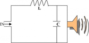
The two capacitors are in parallel with the midrange and the inductor is in series with the combination.
This arrangement gives a steep low pass (high cut) filter on the midrange - see attached diagram.
The two capacitors are in parallel with the midrange and the inductor is in series with the combination.
This arrangement gives a steep low pass (high cut) filter on the midrange - see attached diagram.
Attachments
Last edited:
maybe thats why mid's are going like crazy when there is bass'y song sub is moving a lot aswell as mid's maybe they just cut off high pass until like 9000hz for example and let that mid's driver run as full range from like 80hz (or as low as it can go) to 9000hz where tweeter takes in from 9kHz 🙂I've checked out the crossover board connections.
The two capacitors are in parallel with the midrange and the inductor is in series with the combination.
This arrangement gives a steep low pass (high cut) filter on the midrange - see attached diagram.
Perhaps the low frequencies are not supplied to the mid/tweeter assemblies by their dedicated amplifier?
I think you explained earlier that a separate amplifier supplies the low frequencies to the dual voice coil woofer?
I think you explained earlier that a separate amplifier supplies the low frequencies to the dual voice coil woofer?
Because one chip on the pcb has both mid and high outs next to it and second has subwoofer out, on subwoofer plastic cover it says active crossover.🙂Perhaps the low frequencies are not supplied to the mid/tweeter assemblies by their dedicated amplifier?
I think you explained earlier that a separate amplifier supplies the low frequencies to the dual voice coil woofer?
Yes, I remember now that you mentioned an active crossover.
It looks like you could be settling on:
It looks like you could be settling on:
- A film capacitor for the tweeter.
- Better electrolytics for the midrange.
- Improvements to the internal speaker wiring.
- Installing sound absorbent on the enclosure walls.
Does it have to be specific audio MKP capacitor for the tweeter or any polypropylene MKP capacitors will do like for example filtering capacitors?🙂Yes, I remember now that you mentioned an active crossover.
It looks like you could be settling on:
Be sure to let us know how it turns out. 😎
- A film capacitor for the tweeter.
- Better electrolytics for the midrange.
- Improvements to the internal speaker wiring.
- Installing sound absorbent on the enclosure walls.
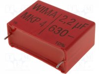
Doesn't necessarily have to be audio specific. Choose one which will best fit your crossover board in terms of physical size and lead spacing.
The higher the voltage rating the better. I've had good results with WIMA polypropylenes like the one shown below.
The higher the voltage rating the better. I've had good results with WIMA polypropylenes like the one shown below.
Attachments
Don´t waste money on capacitors and wire which do almost nothing, certainly nothing audible considering the rest of the setup, and instead invest on better woofer, midrange, tweeters, and mount them in a REAL cabinet.
Sound will improve immensely and you will get return for your money and effort.
No polyfill will help that abysmal :
* undersized
* vibrating flexible walls
* leaky (lots of holes and slots everywhere)
plastic cabinet.
If you want to improve it, do it; throwing money at the current boombox type cabinet will not help you.
So far it´s basically same as:

probably same kind of speakers, exact same cabinet construction and quality, only cassette player has been updated to bluetooth.
Oh, and a class D amplifier ... but acoustic components which are the weak point are basically the same.
Sound will improve immensely and you will get return for your money and effort.
No polyfill will help that abysmal :
* undersized
* vibrating flexible walls
* leaky (lots of holes and slots everywhere)
plastic cabinet.
If you want to improve it, do it; throwing money at the current boombox type cabinet will not help you.
So far it´s basically same as:
probably same kind of speakers, exact same cabinet construction and quality, only cassette player has been updated to bluetooth.
Oh, and a class D amplifier ... but acoustic components which are the weak point are basically the same.
Yes but if i mount them in a real ''cabinet'' it won't be counting as portable then since the weight will be not 7kg like it is now but minimum 10kg or more since wood like mdf board weights more than plastic, a lot more. Would invest in better drivers but i dont know the dB of current drivers for example tweeter 100dB and mid 97dB and if i buy tweeter 100dB and mid 100dB it will sound worse than it is now🙂 PS. Aiwa advertises it as boombox - and it is new age boombox just some upgrades over current bluetooth speakers.Don´t waste money on capacitors and wire which do almost nothing, certainly nothing audible considering the rest of the setup, and instead invest on better woofer, midrange, tweeters, and mount them in a REAL cabinet.
Sound will improve immensely and you will get return for your money and effort.
No polyfill will help that abysmal :
* undersized
* vibrating flexible walls
* leaky (lots of holes and slots everywhere)
plastic cabinet.
If you want to improve it, do it; throwing money at the current boombox type cabinet will not help you.
So far it´s basically same as:
An externally hosted image should be here but it was not working when we last tested it.
probably same kind of speakers, exact same cabinet construction and quality, only cassette player has been updated to bluetooth.
Oh, and a class D amplifier ... but acoustic components which are the weak point are basically the same.
@ Sonyzz - Please do not quote the entire previous post as it makes the thread difficult to navigate - see forum rules. 😎
JMFahey makes the same points as I have made regarding capacitors, wiring and polyfill.
It appears you will go ahead regardless, but at least will do it affordably! 🙂
JMFahey makes the same points as I have made regarding capacitors, wiring and polyfill.
It appears you will go ahead regardless, but at least will do it affordably! 🙂
got myself a generic transistor tester https://images-na.ssl-images-amazon.com/images/I/71r8rAg75tL._SL1500_.jpg to compare nichicon and ''stock'' bipolar electrolytic capacitors as it shows esr on 10uF 50v nichicon it shows 11.32uF vloss 0.6% and esr of 0.10 ohms will compare that tommorow against ''stock'' yontex capacitors inside, also what will happen if i change mid driver capacitors to polypropylene aswell, will it be better or it won't make a difference against good quality bipolar electrolytics like nichicons? 🙂MFahey makes the same points as I have made regarding capacitors, wiring and polyfill.
It appears you will go ahead regardless, but at least will do it affordably! 🙂
Also what i found strange is that if crossover uses second order with 12.2uF cap on midrange with inductor the midrange driver gets high freq cut off at like 1150HzI've checked out the crossover board connections.
The two capacitors are in parallel with the midrange and the inductor is in series with the combination.
This arrangement gives a steep low pass (high cut) filter on the midrange.
An externally hosted image should be here but it was not working when we last tested it.
and if crossover uses first order for tweeter with 4.7uF cap - tweeter gets low freq cut off at like 4200Hz
An externally hosted image should be here but it was not working when we last tested it.
so when question is where is the remaining 1150Hz-4200Hz frequency gone or i dont understand something here and make stupid questions 😕😕
That looks like a neat little multifunction tester - available in the UK for £24.
I've already stated that I don't think that changing the crossover capacitors in your particular unit will make any audible difference. You are free to prove me wrong by actually comparing different types for yourself!
Re crossover frequencies: (a) I can't get your images to open, and, (b) I can make no comment without knowing the inductor value and the impedance characteristics of the midrange and tweeter drivers.
P.S. I'm more concerned that you appear not to accept some of my stupid answers! 😉
I've already stated that I don't think that changing the crossover capacitors in your particular unit will make any audible difference. You are free to prove me wrong by actually comparing different types for yourself!
Re crossover frequencies: (a) I can't get your images to open, and, (b) I can make no comment without knowing the inductor value and the impedance characteristics of the midrange and tweeter drivers.
Am I correct in thinking you are fairly new to electronics as a hobby?or i dont understand something here and make stupid questions 😕😕
P.S. I'm more concerned that you appear not to accept some of my stupid answers! 😉
A: Picture No.1 mid.png - Google Drive Picture No.2 high.png - Google DriveThat looks like a neat little multifunction tester - available in the UK for £24.
I've already stated that I don't think that changing the crossover capacitors in your particular unit will make any audible difference. You are free to prove me wrong by actually comparing different types for yourself!
Re crossover frequencies: (a) I can't get your images to open, and, (b) I can make no comment without knowing the inductor value and the impedance characteristics of the midrange and tweeter drivers.
Am I correct in thinking you are fairly new to electronics as a hobby?
P.S. I'm more concerned that you appear not to accept some of my stupid answers! 😉
B: Inductor is 1.35mH and uses steel plates as its core (i've shorted the leads together for calibration then measured inductor twice) IMG_20181108_153020.jpg - Google Drive Tweeter is 8ohms 10w IMG_20181108_152019.jpg - Google Drive Midrange Driver is 8 ohms 20w IMG_20181108_152406.jpg - Google Drive
ps. here on the subwoofer ring it says ''active crossover'' https://drive.google.com/open?id=1nRSFZxGngOq-TWA449_ZFn9E9ZvQGyOJ
and here is two TPA3118 class D amplifiers with its outputs left one driving subwoofer (dual coil), right one - driving mid's and high's https://drive.google.com/open?id=1XcFtOnPZvs1A1Vk4JgOa-eD8vV-60WDX 🙂
not a hardcore electronics hobbyist but i did some simple and little bit complex projects in the past and was on hiatus for a while (since parts cost and space limitations in the new house abroad), i was not in to crossover stage and just recently (couple months ago lol) started really watching videos about it and reading forums watching reviews, tests, etc. - i'm just amateur 🙂
Last edited:
Thanks, it's handy to know that. I'm only amateur status myself, but I have been dabbling in audio for a long time!not a hardcore electronics hobbyist . . . i'm just amateur 🙂
Will take a look at your pics to see if I've anything further to add to the discussion.
This is a kind of a situation where many amateur diyers land while dreaming of improving sonics. I know for certain that it is pretty hard to improve on the sound of such a product, and one can pull it off after one figures all the things that count in this business. My advice is to exchange the caps if necessary and that means only in the case of being faulty, otherwise leave it as it is.
Your interpretation of the crossover circuits is correct. I wouldn't worry about the exact value of the inductor.
It would appear that the midrange starts to droop around 1.2kHz and the tweeter comes in below 4.2kHz. (Remember that the filters act on the drivers gradually and not exactly at the frequencies you have calculated.) The two drivers will overlap for a while.
The output of the midrange cone will begin to fall away, leaving the job of reproducing the higher frequencies to the tweeter cone.
Make sure you seal up the midrange enclosure when you are finished to ensure it is air tight. If there was no polyfill in the mid enclosure to begin with, then now is a good time to add a little.
Last edited:
- Status
- Not open for further replies.
- Home
- Loudspeakers
- Multi-Way
- Electrolytic bipolar capacitors in passive crossover?