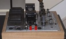
Looks like someone has already done some DIY. 2 mono amps -- likely from 2 organs (rare to find a console with that much power and unlikely dual mono) built into a common chassis.
Your pic is small, can you post a larger one, and of the top, and inside?
dave
Your pic is small, can you post a larger one, and of the top, and inside?
dave
What I would like to do is rebuild it on another chassis and get rid of the extra sockets. Just don't know if outputs are good for audio
That does look like it is original… the wood parts were either added or Electrohome shipped it as a stand-alone amp.
dave
dave
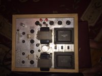
Think I will with a better preamp section, if anyone could help with schematic that would be great. Power transformers are different and trying to figure out what there powering
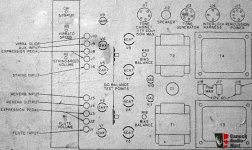
That pictorial diagram clearly shows a musical instrument configuration. Full power bass extension might not be available from the O/P "iron". HF extension is probably OK, given the flute mention.
Either triode wired sets from the EL34/6CA7/KT77 multi-grid group or (specifically) Sovtek 6B4G DHTs, along with a reasonable amount of GNFB, should work well in the PP O/P positions. The reduced power from triode "finals" ensures the magnetic headroom needed to handle the deep bass error correction signal is present.
Mullard style signal topology, along the lines of the H/K Cit. 5, with its high gm small signal emphasis, avoids possible LF instability and provides resistance to HF error correction signal induced slew limiting.
Attachments
All those terms show it was from an organ. The vibra-glide effect identifies it as from an Estey organ. Depending on dates of parts, it could have been made by Magnatone, who Estey purchased in 1959.
I'm pretty sure Electrohome would have retailed or rebadged the organ at the time.
I'm pretty sure Electrohome would have retailed or rebadged the organ at the time.
So the outputs transformers are probably not full frequency?
Mr. Robbins makes an excellent case for that stuff being from an organ. You'd best believe that organs play deep bass. 😉 IMO, it's definitely worth a shot to try for both full power and full range. You can always fall back on triode mode "finals", should it be necessary.
Look the O/P "iron" over to see if UL taps are present. Full pentode mode O/P tubes exhibit max. open loop linearity, when g2 B+ is regulated. Either full pentode or UL, Mullard style circuitry will yield good results.
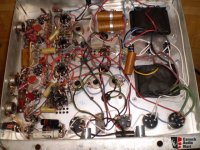
Can a photo of the underside be provided? Maybe we can work out how the OEM B+ PSU is set up.
Usually the difference is whether they are left or right and the length of the wires they are shipped with.
dave
dave
The amps would likely be for different speakers for two manuals (keyboards) that handle different registrations (instruments, effects). One output may need a better treble response than the other - but would still be a wide-range speaker(s).
As such, the difference may be for output impedance - a quick check of each OT turns ratio would show that up (as the valve output stage would be the same nominal PP impedance).
As such, the difference may be for output impedance - a quick check of each OT turns ratio would show that up (as the valve output stage would be the same nominal PP impedance).
This was common in these (and console) amps where the transformers were ordered specifically for production with leads pre-cut to the right length -- i have run across many examples.
dave
dave
Hi refrigman,
Sounds like you have a great project with the donor amplifier chassis. Smile and build away! The Citation V is a fairly generic schematic that should work fine with what you have.
One thing that you could do to increase your reliability would be to drill ventilation holes around the power tubes (suggest 6CA7s). Also above any power resistors that dissipate heat. Easier to do with the unpopulated chassis. You can see this done with many of the better amplifiers. I know it is a pain to drill he holes so they look good, but an over-heating amplifier is no fun to own. You can make the holes around the tubes rather than in a big line. Just make sure the heat can get out and the cooler air can flow in easily.
-Chris
- Home
- Amplifiers
- Tubes / Valves
- Electrohome console amp?