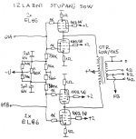
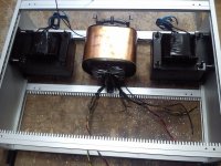
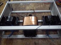
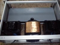
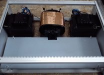
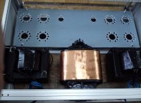
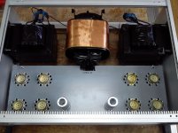
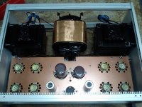
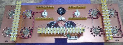
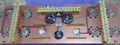
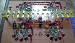
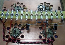
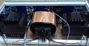
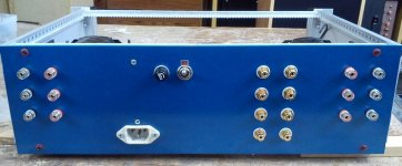
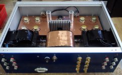
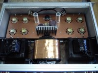
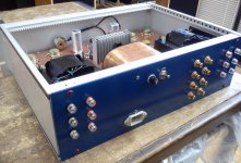
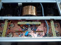
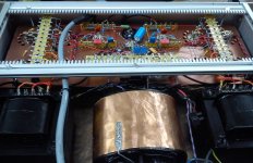
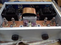
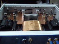
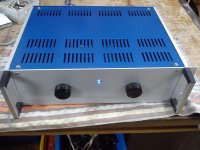
Simple and relatively cheap stereo integrated amplifier with parallel EL86 (6CW5) in push-pull pentodes output stage and ECC83 (12AX7) in phase inverter.
Attachments
-
 002-b.jpg125.1 KB · Views: 1,553
 -
 004ac.jpg426.6 KB · Views: 935
 -
 004b.jpg321.5 KB · Views: 837
 -
 003b.jpg666.5 KB · Views: 815
 -
 002f.jpg127.1 KB · Views: 906
 -
 007a.jpg215.3 KB · Views: 503
 -
 009a.jpg233.4 KB · Views: 326
 -
 012a.jpg168.7 KB · Views: 278
 -
 011a.jpg168.1 KB · Views: 256
 -
 013a.jpg223 KB · Views: 436
...continue...
Attachments
-
 014a.jpg211.1 KB · Views: 239
 -
 016a.jpg200 KB · Views: 182
 -
 002a.jpg232.9 KB · Views: 204
 -
 001a.jpg146.3 KB · Views: 177
 -
 003a.jpg149.1 KB · Views: 189
 -
 005a.jpg172.5 KB · Views: 198
 -
 006a.jpg202.5 KB · Views: 240
 -
 007a.jpg200.6 KB · Views: 256
 -
 008a.jpg225 KB · Views: 208
 -
 009a.jpg272.5 KB · Views: 215
... and more...
Attachments
-
 006a.jpg135.9 KB · Views: 207
 -
 007a.jpg137.1 KB · Views: 186
 -
 010a.jpg171.5 KB · Views: 164
 -
 013a.jpg138.5 KB · Views: 166
 -
 011a.jpg170.4 KB · Views: 144
 -
 012a.jpg191.5 KB · Views: 178
 -
 014a.jpg173.5 KB · Views: 168
 -
 015a.jpg218.1 KB · Views: 201
 -
 001c.jpg385.6 KB · Views: 204
 -
 003c.jpg308.3 KB · Views: 207

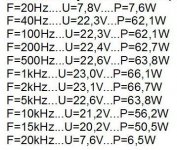
The measurement results of output power on non-inductance resistor 8 Ohm / 100W with sinusoidal signal (Ua~310-320V, Ug2=235V, Ia0=20mA/tube, NFB~10dB and THD~2%):
Attachments
Last edited:
A question and a comment:
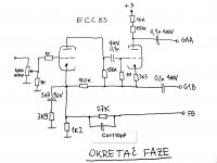
1. Why is the phase splitter unbalanced by 150k in the cathode and 160k in the anode?
2. With perhaps quite a low anode voltage on the first triode, will grid current be a problem at mid volume levels where the volume pot has significant output impedance? Have you tested for how distortion changes with volume pot position?
If you look at it like this, more clear ?The anode of the first triode is not powered !
Typo ? or explain !
Yves.
Mona
Attachments
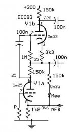
1.Additional resistor of 10kohms just a balancing phase splitter! The entire phase splitter is actually released and published by PHILIPS earlys '60s of the last century as the last one was made with electronic tubes.A question and a comment:
1. Why is the phase splitter unbalanced by 150k in the cathode and 160k in the anode?
2. With perhaps quite a low anode voltage on the first triode, will grid current be a problem at mid volume levels where the volume pot has significant output impedance? Have you tested for how distortion changes with volume pot position?
2.The combination of negative and positive feedback actually phase splitter makes distortion independent in a very wide dynamic range of input signals. Supply voltages Ua-k each triode is actually very little change (change alternately to the ground and the positive supply voltage) regardless of the input (and output) level, thanks to the alternating action of feedback (positive and negative) connections. Partially this is a thanks that the output tubes for full power are not need a high voltage on the G1 (~ 15Veff).
At the lower level of the potentiometer are distortion lower, generally in proportion with power output.
1. OK I see now that the extra 10k is roughly balancing the cathode feedback point.
2. The bootstrap of the anode resistor will lead to low distortion in the first triode. I don't dispute that. What I was concerned about is grid current distorting the signal before it reaches the first triode. If you run an ECC83 at lowish anode voltage then it will have quite a small grid-cathode bias voltage, unless you are running it at unusually low anode current. An ECC83 with small grid-cathode bias voltage is likely to suffer from grid current, which will distort input signals unless the source impedance is low. Note that this distortion will probably be highish order; low order distortion (2nd) may be improved!
2. The bootstrap of the anode resistor will lead to low distortion in the first triode. I don't dispute that. What I was concerned about is grid current distorting the signal before it reaches the first triode. If you run an ECC83 at lowish anode voltage then it will have quite a small grid-cathode bias voltage, unless you are running it at unusually low anode current. An ECC83 with small grid-cathode bias voltage is likely to suffer from grid current, which will distort input signals unless the source impedance is low. Note that this distortion will probably be highish order; low order distortion (2nd) may be improved!
Measurements I performed with "Neutrik A2-D", and yes, noticed the higher order harmonics (5th, and 7th), but not particularly higher than other push-pull amplifier with pentode in output. 2nd harmonic was very low (also commonly used for push-pull pentode), 4th is not worth mentioning, and the main cause of distortion is the 3rd harmonic.
What was the volume pot position for your tests? Distortion due to grid current will be maximised at -6dB setting. You may see a reduction of 2nd and a rise in high orders.
When measuring frequency range, input sensitivity, intermodulation and linearity amplification, potentiometer was completely open, and the input level is regulated by the measuring equipment (audio analyzer), but in measuring the distortion with the criterion of D = 2%, the position of the potentiometer is varied.
The cause of this kind of non-linearity in the border areas of the frequency output transformer which has no sufficient cross-section of the iron core and inductance for low frequency and relatively easily designed and has too few sections for ultra-sound frequencies.
Using high-quality output transformer would be lost economical and relatively low cost of implementation.
Simple and relatively cheap stereo integrated ****************
You have made an amplifier excelent. Congratulate this achievement
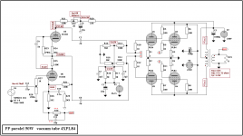
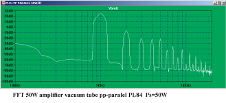
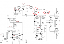
Thought it can be done cheaper using tubes PL84, making a simulation in a schematic LT.Spice equipped with PL84 we obtained the results below:
I hope you do not mind!
Attachments


Last edited:
There is something curious going on here.Max output with a swing of 24V out of the phase splitter means Va=10V on U6 at ½mA.How do you do that with an ECC83 ? Grid current ?
Mona
Mona
There is something curious going on here.Max output with a swing of 24V out of the phase splitter means Va=10V on U6 at ½mA.How do you do that with an ECC83 ? Grid current ?
Mona
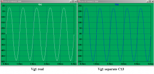
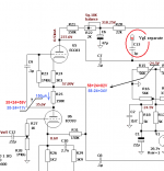
For clarification we put two measurements:
a measurement directly G1 and a measurement separated by C13.
C13 is for tests and measurements.
PL84, the final stage, not working in the current grid.
Sorry, I should specify at the outset.
Attachments
Last edited:
- Status
- Not open for further replies.
- Home
- Amplifiers
- Tubes / Valves
- EL86: push-pull for home