Hi
I'm back...
Its up and running, now I'm hoping I can "improve" on it.
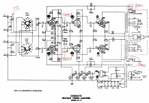
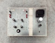
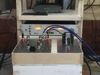
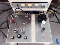
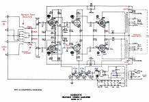
Put it all together in a "box" which makes it a bit easier to move around. The amp has a 1M pot on the volume - I've attached schematic. Given the lower impedance of modern sources and the high output of them, I'm wondering if lowering the value of the volume pot will help in reducing the "brightness" of the amp? I put a voltage divider on the input signal to try and reduce the incoming signal strength ( brought the 2v down to a 1.4v...) It helped a bit with the overall distortion, but I'm finding it a bit bright. I removed the tone controls, but will be putting them back in with a bypass switch should I wish to not use it anymore. I realize I can change the tonal signature using those, but seeing as I want to replace the 60 year old pot with a new one anyway, thought I would see if a different value would help. And ideally, I would like it to sound good without any tone control.
Reading about potentiometers and input impedance is causing me a bit of confusion, which is not difficult to do. Any experience you might have to share would be greatly appreciated.
And, I'm thinking of adding another output tube on each channel in order to increase the output signal strength so I don't have to "push" the amp so close to distortion levels. I've been looking at schematics that have EL84's run in a parallel SET configuration and it seems like it might be possible to do with this amp? I have the space for the extra tubes. Guess I'm wondering if the output transformer is going to be able to handle the additional power? I have no idea what the output transformers are rated at unfortunately.
Thanks for taking the time to read through this.
Per
I'm back...
Its up and running, now I'm hoping I can "improve" on it.
Put it all together in a "box" which makes it a bit easier to move around. The amp has a 1M pot on the volume - I've attached schematic. Given the lower impedance of modern sources and the high output of them, I'm wondering if lowering the value of the volume pot will help in reducing the "brightness" of the amp? I put a voltage divider on the input signal to try and reduce the incoming signal strength ( brought the 2v down to a 1.4v...) It helped a bit with the overall distortion, but I'm finding it a bit bright. I removed the tone controls, but will be putting them back in with a bypass switch should I wish to not use it anymore. I realize I can change the tonal signature using those, but seeing as I want to replace the 60 year old pot with a new one anyway, thought I would see if a different value would help. And ideally, I would like it to sound good without any tone control.
Reading about potentiometers and input impedance is causing me a bit of confusion, which is not difficult to do. Any experience you might have to share would be greatly appreciated.
And, I'm thinking of adding another output tube on each channel in order to increase the output signal strength so I don't have to "push" the amp so close to distortion levels. I've been looking at schematics that have EL84's run in a parallel SET configuration and it seems like it might be possible to do with this amp? I have the space for the extra tubes. Guess I'm wondering if the output transformer is going to be able to handle the additional power? I have no idea what the output transformers are rated at unfortunately.
Thanks for taking the time to read through this.
Per
Attachments
perkri,
That looks very nice!
Did you remember to make a very good electrical connection between the two metal chassis.
Safety First!
Prevent the "Surviving Spouse Syndrome".
1. . . . I thought this was already an earlier thread.
Did you start a new one, instead of adding to the old thread?
. . . Or did a Forum Administrator start this new thread for you, because it is so different from the original thread?
2. You do not just add another tube (in parallel), without changing a lot of other things.
More output power does not come for free.
3. Typically, to parallel the output tubes to get more power, you need the following:
More B+ current
More filament current for additional output tubes and for additional rectifier.
Bigger power transformer
Parallel rectifier; or beefier rectifier (which will need a 5V filament transformer)
A bigger output transformer (several parameters have to change)
And often, more drive current from the driver stage
4. You have to determine what is making the sound "bright"
Amplifier damping factor
Amplifier frequency response
Amplifier harmonic distortion
Amplifier intermodulation distortion
These require that measurements be made (test and measurement equipment).
Speaker specifications (just the make and model number sometimes helps).
Adjustment of speaker mid and high frequency level controls, if present
Speaker / Amplifier interaction
Room acoustics
Worn out phono cartridge (worn diamond, or hardened 'rubber' suspension that holds the needle cantilever)
Signal sources, including recording engineers who have lost their high frequency hearing.
Etc.
5. Try another amplifier on the same speakers, room, and recordings.
Try a solid state amplifier
Try another tube amplifier
6. I have not used tone controls on my vacuum tube amplifiers, since when I started using tubes again in 1996.
Hopefully, you can make your tube amplifier sound the way you like without tone controls.
Happy discovery process!
Last edited:
Thanks for all that 🙂perkri,
1. . . . I thought this was an earlier thread.
Did you start a new one, instead of adding to the old thread?
2. You do not just add another tube (in parallel), without changing a lot of other things.
More output power does not come for free.
3. Typically, to parallel the output tubes to get more power, you need the following:
More B+ current
More filament current
Bigger power transformer
A bigger output transformer (several parameters have to change)
And often, more drive current from the driver stage
4. You have to determine what is making the sound "bright"
Speaker / Amplifier interaction
Amplifier damping factor
Amplifier frequency response
Amplifier harmonic distortion
Amplifier intermodulation distortion
Speakers
Room acoustics
Worn out phono cartridge (worn diamond, or hardened 'rubber' suspension that holds the needle cantilever)
Signal sources, including recording engineers who have lost their high frequency hearing.
Etc.
These require that measurements be made (test and measurement equipment)
5. Try another amplifier on the same speakers, room, and recordings.
Try a solid state amplifier
Try another tube amplifier
Happy discovery process!
1) Yes, started a new thread as new "issues". Figured that might be in order 🙂
2) Kinda figured that was the case.
3) Was hoping the power/output transformers would be up to the "challenge". And I was hoping the 7199 tubes would be able to provide the additional current to drive the power tubes. They are happy with a very small input from what I gather?
4) I have tried the amp with 5 different pairs of speakers and the problem of "bright" is present with all of them (Minimus 7's, DIY FF85's, DIY CX120's, ESL57's and Cornwalls). My main amp is a Cary SLI-50, I also use a Marantz 2230 (fully rebuilt) a Topping MX3 (which is really for the TV and a 15W aliexpress "special"... The EL84 is particularly bright compared to the others, and particularly so with the phono stage (which does not exhibit the same problems through the other amps - McCormack Micro Phono Drive). So I started wondering if it could be a problem with loading? The cartridge is about 3 months old and runs wonderfully through the other amps. I believe the TT (re-engineered L70 in heavy plinth w/SME 3009 which I built) is indeed properly set up - I tend to be a bit obsessive about details.
All this to say, the amp is most definitely bright 🙂
I would imagine there could be a dozen reasons why its bright and as I never listened to the SA-3 with any kind of critical ear before I stripped it down as it was so noisy, it could very well be the timbre of the amp. But the amp was built to the schematic and voltages are a off - perhaps this is why?
(I've added a copy of schematic with the voltages as they are now)
Thanks again!
Per
Most magnetic phono cartridges . . .
1. Need to see a 47k Ohm resistive load, and the parallel capacitance that is no more than 250pF to 350 pF (including the cable in the tone arm, and the cable to the amplifier input, plus the input capacitance of the amplifier circuit).
The total capacitance resonates with the cartridge's coil inductance.
A resonance that is in the upper mid frequencies, or in the higher frequencies can sound bright.
Also, there needs to be an RIAA frequency compensation to make the magnetic phono cartridge plus the record have a flat frequency response. The record was recorded with the RIAA curve, to Accentuate the amplitude of the high frequencies, and decrease the amplitude of the bass frequencies. A proper phono preamp has the Inverse RIAA curve, to flatten out the frequencies, so it is not bright, and so that it has the bass restored.
Your tube amplifier does not have the Inverse RIAA curve.
Unless you are using an external phono preamp with that tube amplifier, the sound will be . . . Bright.
Thanks!
Yeah, I'm kinda aware of RIAA phono stages 🙂
As I said, I'm using a McCormack Micro Phono Drive, and the cartridge is a Ortofon LVB. My previous cartridge, which I wore out, was a standard 2M Black. And I do not have this brightens with any of the amps or speakers. Just this amp.
Like I said, it could very well just be how this sounds, but I suspect there is something that is not as it should be. Everything is brighter, but the phono more so. The tuner is the least offensive (Magnum Dynalab FT 101A that was upgraded by MD to Etude - and after talking to the owner at MD, I did some further changes to the tuner. That might account for it not being as bright)
My digital input - which goes through a Theta Cobalt 307 has what I can only describe as a typical "digital" sound when compared to the Phono.
I'm putting the tone controls back in for now - along with a fuse (figured that might be a good idea) - and will keep on doing research.
Per
It is pretty hard to guess what the actual amplifier frequency response is . . .
With, and without, the tone controls.
With the particular output transformers
With the particular negative feedback resistors and compensation cap
If you took out the bass tone control, C17 & R29, you have to connect the 'parallel feedback resistor and capacitor' directly to the secondary 16 Ohm output tap.
If you did not connect the feedback network R21 & C13 to the 16 Ohm tap, all bets are off.
Frequency response, harmonic distortion and intermodulation distortion, damping, etc. All bad, and probably bright.
If you want to use the 8 Ohm or the 4 Ohm taps to connect R21 & C13, you need to adjust the resistance and capacitance for the same voltage division, and phase compensation (actually the phase compensation is complicated, the leakage reactance from the primary to the 16, 8, and 4 Ohm secondaries is not the same).
With the tone controls out, and the feedback in (correctly), then you might try this:
Try connecting the speakers to the tap that is less than the speaker rating.
Example, a 16 Ohm speaker to the 8 Ohm tap, an 8 or a 6 Ohm speaker to the 4 Ohm tap.
Last edited:
Hey,
I did have the 16ohm tap connected through a straight wire in order to keep the NFB working.
Just finished installing the pots/caps for the tone controls (an a fuse...)
Waiting for the amp to warm up, and I'm then going to have a critical listening "moment" 🙂
Right off the bat, the brightness is gone.
The mids have lost a little sparkle, but I'll wait for it to warm up before I judge it.
The caps are all new, and the treble/bass caps are without any time on them at all.
Thank you again for taking the time to help me through this.
I'll be following up with a more detailed description once its settled in.
Per
Morning.
So far so good! The “brittle” high end is gone! Bass got very boomy after putting the tone controls back in. If it’s not one thing, it’s another 🙂 Put some .1uF caps in place of the .01uF’s (C17 &C18) and that resolved the boomy bass.
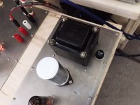
I also picked up a low level hum after installing the tone pots and fuse. Suspect I may need to re route some wires. It’s a constant and quiet tone which isn’t effected by volume. Could be the fuse too close to the power transformer, but I’m just guessing. More research for later 🙂 Tone controls on either side of volume at the front and you can see where the fuse socket was put. Not the smartest move…
So far so good! The “brittle” high end is gone! Bass got very boomy after putting the tone controls back in. If it’s not one thing, it’s another 🙂 Put some .1uF caps in place of the .01uF’s (C17 &C18) and that resolved the boomy bass.
I also picked up a low level hum after installing the tone pots and fuse. Suspect I may need to re route some wires. It’s a constant and quiet tone which isn’t effected by volume. Could be the fuse too close to the power transformer, but I’m just guessing. More research for later 🙂 Tone controls on either side of volume at the front and you can see where the fuse socket was put. Not the smartest move…
Attachments
That is progress!
Now, Hum . . . Equally on both channels?
Or more on the output transformer that is closest to the power transformer?
What is the angular orientation of the output transformer relative to the power transformer?
Take a 1k Ohm resistor, connect it from EL84 Pin 2, to ground at the ground end of R25.
Did the hum go away?
Take a 1k Ohm resistor, connect it from 7199 Pin 9, to ground at the ground end of . . . R18?
I can not read the schematic R number, but it is the resistor that connects from the 7199 cathode, pin 8, to ground.
Did the hum go away?
These things may tell us much more about the cause/source of the hum.
Hey,
Hum is exactly the same on both channels.
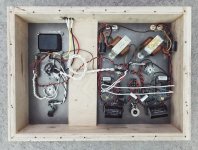
Output transformers are quite far away from the power transformer and the are under the amp while the power transformer is on top. Output transformers are rotated so as to hopefully reduce any interference. See photos
And as I mentioned, the hum was not there before the tone pots/caps or fuse were put in.
But I will find some 1K resistors and install to check on both the 7199 and the EL84
Thanks!
Per
Hum is exactly the same on both channels.
Output transformers are quite far away from the power transformer and the are under the amp while the power transformer is on top. Output transformers are rotated so as to hopefully reduce any interference. See photos
And as I mentioned, the hum was not there before the tone pots/caps or fuse were put in.
But I will find some 1K resistors and install to check on both the 7199 and the EL84
Thanks!
Per
Attachments


Heres another one...
Should I be concerned about the voltages not matching the specified voltages in the schematic?
Wondering if this could be compounding the distortion that is still there, albeit at higher volume levels...

Should I be concerned about the voltages not matching the specified voltages in the schematic?
Wondering if this could be compounding the distortion that is still there, albeit at higher volume levels...
I see the original bass control was part of the negative feedback loop. Did you remove that whole loop from the 16ohm tap to the input tube cathode? Tuning on that feedback loop or replacing it with plate to plate "schade" feedback will be a way of tuning the tone of the amp.Hi
I removed the tone controls, but will be putting them back in with a bypass switch should I wish to not use it anymore. I realize I can change the tonal signature using those, but seeing as I want to replace the 60 year old pot with a new one anyway, thought I would see if a different value would help. And ideally, I would like it to sound good without any tone control.
Per
1. Just connect one resistor at a time; and one channel at a time.
(before/after test is easy, because if you only do the Left channel, the Right channel is un-modified; compare the relative hum levels, L to R).
I should have said to connect the 1k resistor to the 7199 pin 9 first. Check for hum, and how strong it is.
Then disconnect that 1k from the 7199; and connect it to the EL84 next. Check for hum and how strong it is.
2. That Heathkit was made for 117V.
If your line voltage is 121V, that is 121 / 117 = 1.0342
1.0342 x 270V = 279.2V
You can see, an old 117VAC transformer puts out more voltage when you use 121VAC mains.
That is why all your voltages are high, right?
Hi Stephe,I see the original bass control was part of the negative feedback loop. Did you remove that whole loop from the 16ohm tap to the input tube cathode? Tuning on that feedback loop or replacing it with plate to plate "schade" feedback will be a way of tuning the tone of the amp.
I did run a wire from the 16ohm output of the transformer to R21/C13 & R25/C16 🙂 Been doing a bit of mucking about with it and it seems to be getting better with every little change I make. I will look into the "schade" feedback as an option! I put a "substantial" voltage divider in front of the circuit so as to drop the input voltage down to approx. 100ma from the line level (My tuner has a 1 volt line level, so I based it on that...) I put the tone controls back in and have been playing with the capacitor values and for now, it seems to be much better! Distortion is seriously reduced (but given I have no way of measuring it, its based on my hearing...) and the brittle/bright high end is much better controlled. My "stress test" for treble is Bill Charlaps "Blue Orchids" from his "Stardust" record. Reproducing the piano is no small feat, and the amp seems to be working OK.
I'm wondering if I am asking too much from this little thing. Only tube SE amp i have access to so I have nothing to compare it to, guess I'll have to build another one.
Love your instructional You Tube channel! It was after watching your videos that I made the leap and tore down the SA-3 to its bare bits. Thanks for that!!!
Per
Attachments
Morning!1. Just connect one resistor at a time; and one channel at a time.
(before/after test is easy, because if you only do the Left channel, the Right channel is un-modified; compare the relative hum levels, L to R).
I should have said to connect the 1k resistor to the 7199 pin 9 first. Check for hum, and how strong it is.
Then disconnect that 1k from the 7199; and connect it to the EL84 next. Check for hum and how strong it is.
2. That Heathkit was made for 117V.
If your line voltage is 121V, that is 121 / 117 = 1.0342
1.0342 x 270V = 279.2V
You can see, an old 117VAC transformer puts out more voltage when you use 121VAC mains.
That is why all your voltages are high, right?
Going to give it a whirl once I get some 1K resistors. My "inventory" is a bit limited 🙂 And the comment on the voltage situation makes absolute sense. I just measured and I have 123.3VAC here, so that leaves me with 284.5... So yeah, that would explain a lot, thanks for that!!!
The hum is VERY quiet and is all coming from the woofer. It is just barely audible from my listening position, but I know that it should not be there. I bypassed the fuse to see if that was the culprit, but that made no difference at all. I mounted the power transformer to chassis using rubber washers so as to help manage vibrations. The transformer does have an intermittent mechanical buzzing, but I suspect that is due to not being able to tighten it down properly because of the rubber washers. It stops if I tap the transformer, and has not been there for a couple of days.
Per
Did some research, and measured the hum from the amp. Its a 120Hz tone. Until I get a hold of some 1K resistors, I'm going to check all the ground connections.
Here’s a shocker…
Full disclosure, I am a cable convert. I believe they, like everything else in a system, matter…
After having done more internal voltage measurements and a bit of math, it would seem that the legibility of the copy of the schematic I was working from was a bigger issue than I expected. R26 & R27 were not 39K as I had incorrectly read, but rather 3.9K. R31 was not 47K, but rather 4.7K. The voltages are much closer to what they should be now.
So I felt it was time to do a proper A/B check to see how this little amp compares to my main amp, the Cary SLI-50. I got everything set up, measured the exact spl from both amps using a mono pink noise - wanted this to be as exact as possible. Needles to say, they sounded very different.
The SA-3 rebuild was a lot more sibilant than the SLI-50. The SA presented as having much more air than the SLI and SA appeared to be more transparent. Mids were warmer on SLI and bass was better defined. Which seemed odd as the SA was more analytical on the mid/high end. These were obvious differences that made themselves clear after one song being played through each. (David Sylvians ‘When the Poets Dreamed of Angels‘ from his ‘Secrets of the Beehive’ record). It was getting late so I was going to follow up again in the morning.
Then I thought, wait, the cables used are very different. The SA was connected with some inexpensive diy cables - both RCA and speaker - while the SLI was connected with my Kimber Kables. So, I moved the Kimbers to the SA. The difference was shocking and immediate. At least 90% of the problems I was hearing from the SA went away…
I would never have expected this amount of difference from cables. Some, yes, but this much? Never.
Going to have to check again after the weekend. This kind of sucks, as I’ve been usIng cheap DIY cables for my various builds when shifting gear that isn’t my main set up around. Looks like I may need to upgrade these…
- Home
- Amplifiers
- Tubes / Valves
- EL84 SET integrated volume potentiometer value, and can I add another output tube...