Re: DARLING AND Rk
Aleksandar, of course we are talking about bypassed cathode resistors; I thought that would be assumed...
😕 why not???
You won't know until you try it, will you?
Yes, there is always that theory, and as you say, people are entitled to it. I suppose there are probably people for whom it is true, but I don't buy it on a general basis. Adding an ECC83 to the signal chain will not make an opamp sound like a tube. It might add color, but it won't fix what the opamp destroyed.
My personal belief (which I am entitled to 😉 ) is that good tube equipment is good not because it adds flavor, but because it does not subtract (destroy) subtle information in the signal. Obviously, I don't know exactly what that information is. If I did then I could invent a way to measure it and put an end to these conversations. 🙂
-- Dave
Aleksandar, of course we are talking about bypassed cathode resistors; I thought that would be assumed...
Clipping the Rk's together -- not that I am really willing to open an amp and try that...
😕 why not???
Since Rk's are usually bypassed (in my case), I do not think that there would be much of a difference.
You won't know until you try it, will you?
I also recall reading a letter posted to Sound Practices about the sonic merits of "blonde monsters" -- the hi-fi of yesteryear. The point was that some people prefer (and are obviously entitled to it) sound which is maybe not that true to the source, but suitable to their palats. And, there is no universal truth...
Yes, there is always that theory, and as you say, people are entitled to it. I suppose there are probably people for whom it is true, but I don't buy it on a general basis. Adding an ECC83 to the signal chain will not make an opamp sound like a tube. It might add color, but it won't fix what the opamp destroyed.
My personal belief (which I am entitled to 😉 ) is that good tube equipment is good not because it adds flavor, but because it does not subtract (destroy) subtle information in the signal. Obviously, I don't know exactly what that information is. If I did then I could invent a way to measure it and put an end to these conversations. 🙂
-- Dave
FURTHER...
Dave,
Of course we are talking about bypassed Rk? The problem I addressed in the Zen (or Mulligan, as some call it?) case is ABOUT UNBYPASSED Rk. The supposed mixing of signals, etc. commented above in the thread was about the fact the Zen amp uses one Rk common to the output tubes of both channels, and this single cathode resistor is not bypassed.
Mixing of signals, combined cathode degeneration for channels... name it whatever you like -- it certainly adds some flavour to the sound. And that is something you already said you're against.
Now again about bypassed common (or strapped together) Rk.
I do not have the time to do it! And, I do not have the place to do it! Making anything in the cramped living conditions I am forced to bear for reasons relatively appearent thru this thread requires great motivation and intent -- which I do not lack when it comes to making a new amp, or preamp... especially when I have something new or different on my mind and want to translate the theory to practice. BUT, when it comes to trying something I feel unnecessary, or not leading to any reasonable result -- it would be just a loss of time and energy.
Well, curiously, that is my opinion, too. Since it seems to me that stereo is two separate channels, each carrying an amount of information, I tend to think of any contact between these two channels before being "emmitted" from the loudspeakers to be damaging to the integrity of that signal.
Notwithstanding, we mostly mix them in a lot of places -- from grounding arrangements to common power supplies for both channels (if amps and preamps are not completely monoaural) etc. Some of these "potential mixing" (and mixing it certainly is - although mostly on relatively low levels, i.e. -80dB or more) can be "forgotten about" since at the levels where they occur they should not be audible or quantifiable, and it is either simpler or cheaper or more practical to do it that way... but, if as you assume, a bypassed common resistor would sound differently than two adequate separate bypassed resistors -- than to some logic reasoning it means there is some interaction between the channels.
To me, the less interation there is between the channels, the closer we are to the "truth" of the signal.
Regards to all,
Aleksandar
Dave,
Of course we are talking about bypassed Rk? The problem I addressed in the Zen (or Mulligan, as some call it?) case is ABOUT UNBYPASSED Rk. The supposed mixing of signals, etc. commented above in the thread was about the fact the Zen amp uses one Rk common to the output tubes of both channels, and this single cathode resistor is not bypassed.
Mixing of signals, combined cathode degeneration for channels... name it whatever you like -- it certainly adds some flavour to the sound. And that is something you already said you're against.
Now again about bypassed common (or strapped together) Rk.
I do not have the time to do it! And, I do not have the place to do it! Making anything in the cramped living conditions I am forced to bear for reasons relatively appearent thru this thread requires great motivation and intent -- which I do not lack when it comes to making a new amp, or preamp... especially when I have something new or different on my mind and want to translate the theory to practice. BUT, when it comes to trying something I feel unnecessary, or not leading to any reasonable result -- it would be just a loss of time and energy.
My personal belief (which I am entitled to ) is that good tube equipment is good not because it adds flavor, but because it does not subtract (destroy) subtle information in the signal.
Well, curiously, that is my opinion, too. Since it seems to me that stereo is two separate channels, each carrying an amount of information, I tend to think of any contact between these two channels before being "emmitted" from the loudspeakers to be damaging to the integrity of that signal.
Notwithstanding, we mostly mix them in a lot of places -- from grounding arrangements to common power supplies for both channels (if amps and preamps are not completely monoaural) etc. Some of these "potential mixing" (and mixing it certainly is - although mostly on relatively low levels, i.e. -80dB or more) can be "forgotten about" since at the levels where they occur they should not be audible or quantifiable, and it is either simpler or cheaper or more practical to do it that way... but, if as you assume, a bypassed common resistor would sound differently than two adequate separate bypassed resistors -- than to some logic reasoning it means there is some interaction between the channels.
To me, the less interation there is between the channels, the closer we are to the "truth" of the signal.
Regards to all,
Aleksandar
Re: FURTHER...
Mulligan is the name given to a ZEN-like-clone...
unbypassed Rk? Not in the map i've got.
dave
Alex Kitic said:Of course we are talking about bypassed Rk? The problem I addressed in the Zen (or Mulligan, as some call it?) case is ABOUT UNBYPASSED Rk. The supposed mixing of signals, etc. commented above in the thread was about the fact the Zen amp uses one Rk common to the output tubes of both channels, and this single cathode resistor is not bypassed.
Mulligan is the name given to a ZEN-like-clone...
unbypassed Rk? Not in the map i've got.
dave
Attachments
Originally posted by planet10
Mulligan is the name given to a ZEN-like-clone...
But why 😕
The Zen has an unbypassed cathode resistor common to the output stage of both channels according to the schematic posted on the Decware website. See it here.
bypassed or not?!
Well, I am not at all surprised by this latest revelation... if there were not bypass cap, it would not make much sense -- on one hand, aforementioned channel mixing etc. -- while on the other due to cathode degeneration distortions would be lower but gain limited and the power output into the (same and usual) load would be much lower, as well.
It is true that the Decware website hosts a schematic version (revision C, if I am correct) showing a non-bypassed Rk common to both channels. And, furthermore -- there is a photo of the interior somewhere on the site showing a nice looking resistor with metal coolers -- but no cap near this resistor.
Now, what we might really need is someone who owns the "original" amp ("Would you buy your dad a fake Rolex?" says the site -- if you ask me, better a fake one that shows the correct time, than one that is not fake but does not work, either...). Maybe this person could tell us whether there is a cap (I almost cannot believe that there isn't -- but then the published schematic is in practice dishonest) in the original amp!!!
Aside the discussion on Rk, common or not (maybe necessary, but one I tought would never happen...) is there anyone who has tried both amps?
Regards to all,
Aleksandar
DECWARE Zen Triode Amplifier
Model SE84B
KIT ASSEMBLY INSTRUCTIONS
STEP 51
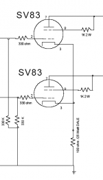
NOTES: The self bias / self balancing circuit used for the output tubes is simple to install. First connect a 4 inch piece of wire between pin 3 on each of the two output tube sockets. Pin 3 is the cathode of the tube and both are connected together to ensure a locked stereo image even when tubes don't match.After you've connected both cathodes together, install the 1000 uf electrolytic cap from pin 3 of either tube to ground. Make sure you get the polarity correct on the cap or it will blow up. Also install a 150 ohm 5 watt resistor across the cap. This is the bias resistor. 150 ohms has been determined to be the best sound. Raising the value to as high as 300 can be done for longer tube life, but probably won't sound as good.
Model SE84B
KIT ASSEMBLY INSTRUCTIONS
STEP 51
NOTES: The self bias / self balancing circuit used for the output tubes is simple to install. First connect a 4 inch piece of wire between pin 3 on each of the two output tube sockets. Pin 3 is the cathode of the tube and both are connected together to ensure a locked stereo image even when tubes don't match.After you've connected both cathodes together, install the 1000 uf electrolytic cap from pin 3 of either tube to ground. Make sure you get the polarity correct on the cap or it will blow up. Also install a 150 ohm 5 watt resistor across the cap. This is the bias resistor. 150 ohms has been determined to be the best sound. Raising the value to as high as 300 can be done for longer tube life, but probably won't sound as good.
Attachments
bypassed or not?
Well, the latest contributions seem to indicate that the by now famous Rk of the output tubes is bypassed. That is quite fine by me -- if you get back to my original comment, I found that a huge, almost impossible flaw, and if the Rk is bypassed, to me it is quite OK.
Since by now everyone seems to ask where did I get the schematics from, here is a link: (I do not know whether the link will work or whether I am entitled to place links, but let's try):
http://www.decware.com/se84cschematic.pdf
I have also attached the file with my post, so anyone can compare it...
Those of you who maybe like the Zen Amp idea better than seeing it critisized by some "audio designer" -- still cannot rejoyce (those addressed have already recognized themselves -- others, please do not find yourselves offended): if the common Rk is bypassed (phew, thank God), that does not mean the driver tube has an adequate operating point, etc. And, unless I somehow missed it in some alternative source, there is no choke in the power supply... etc.
Regards to all,
Aleksandar
Attachments
audiousername said:Mulligan...But why 😕
It just happened one day --> Zen Clone > Bogus Zen > Bogie > Mulligan .... 🙂
Because they are clones they often get souped up pretty quick. My buddies has gone from as close as he could get to the schematic(except for a hybrid bridge)... then PS improvements (including choke), most recently, splitting the EL84s Rk and upping of the driver tube bias (both of which he reports made big improvements)... now on his bench is a pair of parafeed monoblocks (with 5 pieces of iron each)
dave
GeirW said:Just as a "sidenote" to Dave`s post.
(where is you schematic from?)
attached is the latest revision of the 84zen.
(from the manual)
but all revisions seems to be the same, with exeptions
from component values/brand.
My snapshot is from the Zen map i downloaded from the Decware site... i have seen a number of variations of this document but not seen an unbypassed Rk -- i have seen the mod discussed. All 3 of the real Zens that have come thru our local diy hifi group have had bypasses.
dave
RH84 design with regulated Vg2
Mr. Kiticu,
athough your circuits seem quite well elaborated and explained(I wouldn't use the term defended as usual) in this thread,I found a room for little modification.You have connected g2 of the EL84 to the same B+ as the anode is connected,through 2,2K resistor,which in this arrangement yields no benefits(now Vg2 is tracking or "floating" if you want with B+,so there are higher THD and maybe a less output power,IMHO) than if you have the Vg2 regulated with,let's say zener string or better gas tube or maybe even with some HV Fet regulator.For pentode operation it is obviously better to have stiff Vg2 which will contribute to the overall sound improvement.I am sure that,as a designer,you have considered this issue and implementing it or not was maybe due to the final comlexity and costs increasings.Anyway,in these nice amps designs at your site I am undoubtedly and deeply persuaded that this modification will bring fruits.
Regards,
Yugovitz
P.S. Alexandre,can you please remove somehow the ad from the middle of your text of RH807?
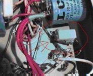
And of course,on the picture Mr. Milan posted on post 67 which is Decware's execution of the Zen amp, I found unpermissible to put up on the bypass cap a 5Watt Rk resistor,which is in close contact!! It is not even good to put it in the close vicinity! Especially if you use expensive caps.The high temperature will ruin every el-cap in the couple of years.
Regards,
Yugovitz
Regards,
Yugovitz
Yugo said:...on the picture Mr. Milan posted on post 67 which is Decware's execution of the Zen amp, I found unpermissible to put up on the bypass cap a 5Watt Rk resistor,which is in close contact!!
Hi,
The picture was taken from the Decware site and used here only to show the bypassed Rk in question. As regards the point you are making, I couldn't agree more but that's a whole other can of worms.
Regards,
Milan
P.S. FYI, your avatar has lost its head over here. But not to worry, they'll screw it back on soon. 😉
Resistors and caps...
Hi, Yugo!
Thank you very much for pointing out the issue with the cap bypassing the Rk on the photo of the Zen Amp posted by Mr. Milan. I saw it right away, but did not want to post just on that issue...
Now for a very interesting question -- the g2 connection.
The g2 is intentionally left as it is, just connected to the B+ supply thru the 2.2k resistor. Why?
1. Theory
Actually, you do not need g2 to be additionally bypassed in order to achieve "pentode mode" since what is necessary is a different AC path (and here it differs by not passing thru the output transformer, while for AC grounding, it is indeed grounded thru the nearest cap of the power supply).
2. Simulation
At first, simulation was executed with the schematics as shown. Further, I tried to improve by connecting the g2 thru a cap to ground, even inserting an additional power supply just for the g2 of the output tube -- but the results did not change a bit.
Now someone could intervene that simulation results are bla..bla.. but interestingly enough, bypassing the g2 to ground did change the simulation results (as expected, improvement) in a later design RH34 (for EL34/6CA7 tubes) which is not published on my web site for stupid reasons -- the web site was meant as non-finished at the time, and by now I think it is time to make some thorough changes to it.
As you can see from my answer, there were no financial reasons involved -- as there never are in my designs, since it is not about kits for sale or anything. A little digression -- why a common Rk on the Zen? Well, one resistor costs less than two, not the mention the price of two bypass capacitors instead of one... 🙂 (I do not actually know whether to laugh, or to cry at this one).
If you are interested in the RH34 schematic, just e-mail me, and I'll send it to you. As I said, the site was never finished -- and by now it is time to make a new one...
A final little issue - as I said, the g2 is connected to the B+ supply thru a resistor. Aside being a "grid stopper" of the sort, actually it tries to keep g2 at the same potential (or similar) as a. I had some toughts about regulating the g2 with 0A2 in a string, or something like that (I would not go as far as making a FET regulator... come on, by now you should know me better than that). But I dismissed the idea since without any further refinement of g2, the amp sounded just fine... sometimes I try not to overcomplicate things.
If the power supply was poorly regulated (by that I mean: not enough current, not enough capacity, high ripple, etc.) in practice it would have great effect to do something with g2. Since that is not the case (and the published version of the power supply is actually the most basic PS done for this amp in its various "incarnations") -- the issue was never addressed, altough it might warrant consideration.
In case any of the thread participants does make one and try it (come on, Planet10 -- your friend might now decide that he could replace the driver tube altogether and add a couple or resistors here and there, making his clone an RH amp!) -- his experimentation with g2 might be a very interesting addition and the very first mod to the RH84 circuitry since it was made!
Regards to all,
Aleksandar
Aleksandre,
I find your experience very interesting regarding the Vg2!Although it differs from mine(it is not maybe as big as yours),but I gained mine through building, servicing mostly guitar amps and reading old tube books borrowed from university's libraries.But what is interesting almost every guitar amp using output pentode in ,normally,pentode mode, has conected its g2 the same way as you did(simplicity,cost issues.....?).And in Hi-Fi amps published on the net on many different sites I found them regulating Vg2 and claiming improvements.IIRC there was a Marantz amp,can't remember the model right now,but I think published in one of the modern ,or if you want more recent books like Rozenblit's or M.Jones' ,which had even a 6l6 used for regulating its Vg2.
For me it is only left to build one of the RH models and to find out myself with little experimenting is it worth to regulate or not.
Considering expences issues I think if regulating is neceserry and if there is no sound difference in using gas tube or fet regulator I wouldn't mind being a tube blasfemist and employ a cheeper and longer lasting SS regulator.Anyway this is DIY audio,mostly used by enthusiasts and people with low budgets.
BTW Alexe,what the abbreviation RH means?
Regards,
Yugovitz
Re: Resistors and caps...
Perhaps this quote, taken for a Decware white paper on design of the phono pre, is part of the rational behind the Zen cathode resistor?:
"I realized while listening that what I was hearing was probably the better stereo separation of the mono blocks. Less perfect separation always enhances the center image (vocals) and makes them glow by super imposing the surrounding ambiance over the center image. That changes the timbre and presence of center image a bit."
Or maybe it's just part of the whole Zen "less is more" thing.
As regards the RH34, anyway you could post the schematic here? I'd guess there are a number of others who would like to see it too.
Sheldon
Alex Kitic said:why a common Rk on the Zen? Well, one resistor costs less than two, not the mention the price of two bypass capacitors instead of one... 🙂 (I do not actually know whether to laugh, or to cry at this one).
If you are interested in the RH34 schematic, just e-mail me, and I'll send it to you. As I said, the site was never finished -- and by now it is time to make a new one...
Perhaps this quote, taken for a Decware white paper on design of the phono pre, is part of the rational behind the Zen cathode resistor?:
"I realized while listening that what I was hearing was probably the better stereo separation of the mono blocks. Less perfect separation always enhances the center image (vocals) and makes them glow by super imposing the surrounding ambiance over the center image. That changes the timbre and presence of center image a bit."
Or maybe it's just part of the whole Zen "less is more" thing.
As regards the RH34, anyway you could post the schematic here? I'd guess there are a number of others who would like to see it too.
Sheldon
Re: Resistors and caps...
You can be sure that one of the mules we have will get fixed up as an RH84 -- i even have an amp with all the requisite tubes in it right now -- just need to get a nasty noise out of it (next up is swapping the filament trafo)... i don't get much spare time so don't hold your breath.
dave
Alex Kitic said:In case any of the thread participants does make one and try it (come on, Planet10 -- your friend might now decide that he could replace the driver tube altogether and add a couple or resistors here and there, making his clone an RH amp!) -- his experimentation with g2 might be a very interesting addition and the very first mod to the RH84 circuitry since it was made!
You can be sure that one of the mules we have will get fixed up as an RH84 -- i even have an amp with all the requisite tubes in it right now -- just need to get a nasty noise out of it (next up is swapping the filament trafo)... i don't get much spare time so don't hold your breath.
dave
Alexsander and all,
I built a stereo RH84 "version" today and only one channel works but it is probably something I missed as tubes are are drawing current so tomorrow I will take a look to see what I missed. Anyway, my version is a bit different from the schematic as I used what I had on hand and what was available on an experimental chassis I have so the differences are (Hammond FX 370?) hexfreds for the rectifiers, 5uf-5H-47uf-1K-47uf which gives me a B+ of 298V, the EL84's are running around 38mA. Also 47uF instead of 10uF for decoupling the 12ax7 plate which has 240R for each Cathode. I am using Hammond 125ESE configured for 5K. Input tubes are ECC83's as I could not find any ECC81's. Speakers were Fostex FE108EZ in Nagaoka Swan 101a's. I did not play it very long because I want to find the problem with the left channel but the first impression was plenty bass not too flabby either and it somehow sounded powerful if thats the right term. Most of the components are almost if not new so it would need some time to relax and run in.
Andrew
Andrewbee said:Input tubes are ECC83's as I could not find any ECC81's.
If you can't find any, i'd be happy to raid my stash & send you a couple.
dave
- Status
- Not open for further replies.
- Home
- Amplifiers
- Tubes / Valves
- EL84 SE design recommendations?