i want to build some how a cheap amp using el84' and found this schematic...
is it ok? values are correct? i find it not reasonable that the OT impedance is 1.25k..mmm...
http://www.bonavolta.ch/hobby/en/audio/el84_4.htm

is it ok? values are correct? i find it not reasonable that the OT impedance is 1.25k..mmm...
http://www.bonavolta.ch/hobby/en/audio/el84_4.htm
Can't see the schem, try posting it again. As for the OPT impedence being 1.25Kohms, it being a quad, each of the tubes "sees" it as 5Kohm impedence (1.25x4=5), so the impedence isn't low at all.
thank you🙂
i think a local company can make it cheaper for me...
just sending 2 cheaper via mail vill be expansive
i think a local company can make it cheaper for me...
just sending 2 cheaper via mail vill be expansive
Good idea. The Hammonds are bigger than necessary and they are quite heavy, too.
Winding a 1,25k/8R OPT shouldn´t be too hard, since winding capacitances etc. becomes less important at lower impedance ratios. With four EL84´s (Ok, 6BQ5´s) in // you won´t need an extremely high primary inductance, 10-15H or so should be enough for a good bass response.
A piece of cake compared to, say, a 10k/8R OPT with 100H prim. inductance.
hello DUD
1. just take in account, this is a Single Ended amp, the power
you can get of this arrangment is about 10 Watt.
2. the output of the driver stage would be better taken
from it's cathode rather than the anode IMHO.
robonibi
1. just take in account, this is a Single Ended amp, the power
you can get of this arrangment is about 10 Watt.
2. the output of the driver stage would be better taken
from it's cathode rather than the anode IMHO.
robonibi
Good point, robo7
If I were to build this circuit I´d change the input/driver stage completely.
Say, one ECC88 per channel with one section as gain stage and the other as cathode follower using direct coupling between the two.
No need for all the gain of a ECC83, but the current capability of a ECC88 would be at hand for driving the input capacitance of the four power tubes.
im a little lost im new in tubes circuits..
can any of you drag the jpeg into the "paint brush" and mark the
changes for me?
can you recommend a better circuit for the first stage?
thank you!!
David
can any of you drag the jpeg into the "paint brush" and mark the
changes for me?
can you recommend a better circuit for the first stage?
thank you!!
David
There is a simpler schem to build at bonavolta's site:
El84 push-pull 1
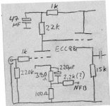
and here is attached my variation on the them. I raised the supply
a little and lowered the current on the o/p pair so you get bit
more power.
El84 push-pull 1
and here is attached my variation on the them. I raised the supply
a little and lowered the current on the o/p pair so you get bit
more power.
Attachments
thank you looks nice!! what kind of sound...?
1.what kind of sound i will expect to get with the tubes above and with the nice circuit you posted?
2. can i parallel 2 more el84's to inc power?(with a 4k primary instead of the 8k)?
i dont want lots of wattage but i think i would like to use 4 in lower power and get more wattage then 2 in max power (longer life right)? 🙂
have a great day🙂 its sunny here
thank you 🙂
i will think how to use it🙂 cos i might use the other circuit robo 7 submitted
can i add 2 more el84 to the schematic above? and lower the primary impedance to 4k?
i will think how to use it🙂 cos i might use the other circuit robo 7 submitted
can i add 2 more el84 to the schematic above? and lower the primary impedance to 4k?
Be my guest.
I´m not sure about the feedback resistor, I don´t have much experience of using NFB. Some trial and error wouldn´t hurt I guess.
I´m not sure about the feedback resistor, I don´t have much experience of using NFB. Some trial and error wouldn´t hurt I guess.
hay DUD,
"what kind of sound i will expect..."
it depends on:
1. the quality of the parts you use.
2. the speakers you wand to drive.
(very)generally speaking, the 84's sound is clear & sweet.
"can i parallel 2 more el84's to inc power"
Yes, "with a 4k primary " as you already wrote.
have a nice day.
Robonibi
- Status
- Not open for further replies.
- Home
- Amplifiers
- Tubes / Valves
- el84 quad schematic..something is wrong...?