Can you measure the voltages at the cathodes of tubes 1 to 6?
12AX7 from the top
tube 1 pin 3 1.97V
pin 8 1.98V
tube 2 pin 3 2.04V
pin 8 2.02V
EL84
top one pin 3 5V
others pin 3 0V
I don't understand.With 5v on the cathode it's in cutoff biased way to cold.
Andy.
Also, please measure the voltage at C9. With the voltage at B1, we can calculate the current through the power supply. If the output tubes are not conducting, the voltage at C9 should be only a little bit higher than at B1.
There is something wrong at the tube with the 5V cathode. With a bias voltage of -5V and a plate voltage of 300V, the current should be much higher, but obviously the current through the cathode resistor is quite low.
If the 6BQ5's cathode bypass electrolytics are fitted mis-polarized, the tube would conduct excessively. The voltages don't show that.
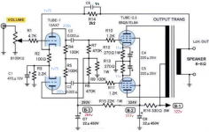
It would be easier for me to help if the schematic had pin numbers.😉 For the 6BQ5's I could look it up, of course. But for the 12AX7's, you could assign either triode to either position in the circuit. Voltages by pin numbers, with no correlation to schematic positions, will limit progress.
Cheers
It would be easier for me to help if the schematic had pin numbers.😉 For the 6BQ5's I could look it up, of course. But for the 12AX7's, you could assign either triode to either position in the circuit. Voltages by pin numbers, with no correlation to schematic positions, will limit progress.
Cheers
Last edited:
The plot thickens.
The voltages at the cathodes of the 12AX7's (and the B+ voltages given in post # 9) seem to indicate that the problem is not caused by the 12AX7's since they seem to pass current. In (only) one of the channels, the top EL84 also seems to pass current, but only 18.5 mA.
If the voltages in post # 9 are those of the channel in which one of the EL84's is passing some current, than the current draw of the 12AX7 + the current draw of the screen grid of that EL84 is about 5 / 330 = 15.2 mA, but the margins are big (because the voltage drop over the 330 Ohm resistor could be a bit more or less than 5 V).
So the little current that only one EL84 is passing, seems to flow entirely through its screengrid. This is in line with TS not hearing anything at all, because if there also was some current flowing to the anode of the EL84, you should at least hear something coming from the amplifier.
So what could be possible is that both output transformers are not connected properly causing the anodes not seeing voltage (and maybe because of that, three of the four screengrids of the EL84's died in the meantime...).
Last edited:
Yep -- +1 PCL200!
15 mA could certainly eat a screen grid.
Wonder if it's time to suggest pulling all tubes but one rectifier and then taking some voltage measurements ..
Regards
15 mA could certainly eat a screen grid.
Wonder if it's time to suggest pulling all tubes but one rectifier and then taking some voltage measurements ..
Regards
Last edited:
Quote:
Originally Posted by Diabolical Artificer
With 5v on the cathode it's in cutoff biased way to cold.
Andy.
I don't understand. A valve is biased negative with regards to cathode, if the voltage is too negative, the valve won't conduct current. The ECC83 at Va 300v Vg1 -4v is drawing little current, it's in cutoff. In most applications ECC83's are biased at about -1.1v.
The 5 V is the cathode voltage of the only EL84 that is passing current (only 18.5 mA, which I suspect is flowing entirely through its screengrid).
...which is in contradiction to OT's measurements in #18: All 6BQ5 plates read voltages well beyond 300 Vdc, but the plate of the one with 5 V cathode voltage is somewhat lower than the three others. I suspect there's something wrong with the screen supply (but I can't see anything that springs into my eye, tbh…).
@OT: Please measure the voltage on all four 6BQ5 #9 pins and report.
Best regards!
@OT: Please measure the voltage on all four 6BQ5 #9 pins and report.
Best regards!
Maybe it is worth also measuring across the cathode resistors (RC1-RC4), to see if there is a voltage drop in each case. That would confirm the cathode current for each tube.
It seems from post # 18 TS already did that, but maybe I don't understand you correctly.
There was the voltage on the pins, but no real idea of the current flowing through the tube. From Mona's post, he should see a 11V drop across each cathode resistor if the tubes are biased OK.
OK, thanks, now I understand.
Additional:
But than it's strange that the B+ measurements from post # 9 seem to indicate that there is a substantial amount of current flowing through the 330 Ohm resistor that doesn't flow through the 12AX7.
But maybe we're looking at more than one problem/mistake?
Additional:
But than it's strange that the B+ measurements from post # 9 seem to indicate that there is a substantial amount of current flowing through the 330 Ohm resistor that doesn't flow through the 12AX7.
But maybe we're looking at more than one problem/mistake?
Last edited:
I'm eagerly awaiting auchamsum's screen voltage measurements. But as there ain't no screen resistors as a possible cause, I tend to suspect that three tubes already have hopped the twig, probably due to a smoked internal jumper between the cathode and it's pin, and the fourth one is taking it's last breath.
Best regards!
Best regards!
Do internal connections (jumpers) between the cathode and the pin in 6BQ5/EL84's (or any tube type) melt (smoke) so often that in one amplfier it can happen to three of the four 6BQ5/EL84's? Is the saturation current of the 6BQ5/EL84 high enough to cause this type of failure? Is this a (widely) known type of failure? To be honest: I never heard of that happening before.
Last edited:
- Home
- Amplifiers
- Tubes / Valves
- EL84 pp amp problem