You can also remove the 100uF cap, it's not really doing anything.
Okay do that
hopefully has no influence on the feedback
Any hints on the 2 x 60v on the trafo mA...?
If i take 50 mA would be right or too high
See need another trafo's one is working other one not and have them on 230ac as well or even 235ac
So have to give the specs of the trafo's to the builder
Last edited:
Hopefully has no influence on the feedback
I doubt it. There is very little voltage developed across such a small resistance so the gain of the stage should primarily be unaffected.
Any hints on the 2 x 60v on the trafo mA...?
If i take 50 mA would be right or too high
See need another trafo's one is working other one not and have them on 230ac as well or even 235ac
So have to give the specs of the trafo's to the builder
Don't you have a working version of the amp, the other monoblock? See what it feeds and find a resistor in series to measure a voltage across, Ohm's Law will tell you what the load is.
Don't you have a working version of the amp, the other monoblock? See what it feeds and find a resistor in series to measure a voltage across, Ohm's Law will tell you what the load is.
Yes ...2 x 60v green wire are on the primairy side of the trafo only
so what it feeds is not know or traceble...thanks a lot for your attention and your time..really appreciated
Last edited:
I think there is some confusion on what 'primary side' means.
The primary is the input of the transformer connected to the mains.
It is not (necessarily) primary taps on the left secondary on the right.
You have to measure electrical continuity (ohmmeter) to be sure which taps on the transformer are part of the primary winding. All windings without continuity to the primary are secondary windings.
I think there is some confusion on what 'primary side' means.
The primary is the input of the transformer connected to the mains.
It is not (necessarily) primary taps on the left secondary on the right.
You have to measure electrical continuity (ohmmeter) to be sure which taps on the transformer are part of the primary winding. All windings without continuity to the primary are secondary windings.
excellent just needed that...
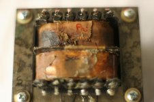
correct: P is primary -see pic - no continuity to the secondairy so the 2x 60 are in the primairy of the trafo..do not understand the purpose okay... but need the mA for trafobuilder
have one block still working on variac 180v > resulting in anode of el84 at 359v... more refined open musical but still produces a lot of heat in powersupply and output transformer....
Attachments
Last edited:
Hi.
EL 84 in triode mode.
Just an experiance no Deep technical thougts 🙂
For about five years ago I had the opportunity to restore a Leak ST20 Power amp.
After the restoration , I was amazed by the sound quality.
The amp is specified to around 10W per channel.
Then I thought wy not go for Triode mode!
Now the EL 84 sings like a Dream.
My speakers is Sonus Faber, not so sensitive but I am so satisfied with the sound.
Around 5-6 Watt or so per channel.
(Running NOS EL84 and ECC 83, Blackburn made) 🙂
?excellent just needed that...
correct: P is primary -see pic - no continuity to the secondairy so the 2x 60 are in the primairy of the trafo..do not understand the purpose okay... but need the mA for trafobuilder
If it is part of the primary it has continuity to it. Could be that the tranny can be wired up for different mains voltages (90,110,120,220,240 something like that).
If there is no continuity to the primary, it is some secondary winding. Where do the wires go?
have one block still working on variac 180v > resulting in anode of el84 at 359v... more refined open musical but still produces a lot of heat in powersupply and output transformer....
What is 'a lot of heat'?
Power transformers can get very hot to the touch but still be in spec. Can you measure the temp? Can you still put your hand (on a side without electrical connections of course).
Output transformers shouldn't get warm, unless it is heat from the EL84s that is warming it up.
Yes ...2 x 60v green wire are on the primairy side of the trafo only
so what it feeds is not know or traceble...thanks a lot for your attention and your time..really appreciated
Hi, I like helping so no worries🙂 I hope you get the amps up and working.
I am still a little confused on why you can't trace where the green wires go😕 If you have a working version of the amp then just follow where the wires go and hook up to. If they just connect to the other primary side pins on the transformer then they are most likely there to connect the windings in parallel or series for 120v or 240v operation.
My opinion is that they are a secondary tap but just placed on the side of the transformer you are calling "primary". My advice is to methodically test continuity to all pins of the transformer and post the results along with voltages. If you have photoshop software you can add these values to the photo you took of the transformer to help us help you. Or if you at least post the results in text form I can edit it to the photo for you when I have time.
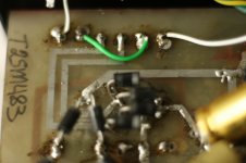
am talking about the green wire connecting pin 2 and pin 5 on the primary side
Trafo in the board
White wire left Pin1 is on of switch
White wire right Pin6 is on off switch
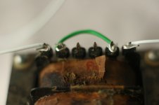
green wire connecting pin 2 and Pin 5 not connected to anything in the circuit just interconnected on the trafo
Pin 3 and Pin 4 are the Bias 13v lines
Trafo in the board
White wire left Pin1 is on of switch
White wire right Pin6 is on off switch
green wire connecting pin 2 and Pin 5 not connected to anything in the circuit just interconnected on the trafo
Pin 3 and Pin 4 are the Bias 13v lines
Attachments
Last edited:
green wire just connects 2 60v windings...need to know if should could stay
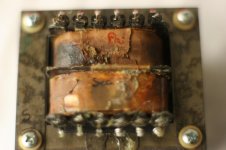
This pic of the trafo is excactly in the same position as it is in the board
Top left Pin 1 is white wire onoff top right is white wire on off named pin
This pic of the trafo is excactly in the same position as it is in the board
Top left Pin 1 is white wire onoff top right is white wire on off named pin
Attachments
Last edited:
I keep seeing questions on the correct load impedance on the output transformer for this amp...what should it be for 8 ohm output? Closer to 5K?
There is no single 'correct' load impedance for a particular triode. There is a range of possibilities, and choosing the 'best' primary impedance is something of a 'taste thing.'
Generally speaking, you'll get the most power from the triode if the transformer primary is chosen for an impedance that is 2X the rp of the triode.
Increase the impedance and maximum power will go down, but so will distortion.
If you draw the load lines, you may find that the max power out is actually achieved with a primary impedance that is higher than 2X the rp of the triode. It depends on a lot of things.
A couple of simple explanations of load lines for triodes with output transformers:
Calculation of SE Triode Amp
Load Line Calculations – wauwatosa tube factory
According to the spec sheets, the rp (plate resistance, also seen as ra or anode resistance in Europe, etc.) of a triode-wired EL84 is about 2k to 2.5k ohms (depending on operating point chosen). So yes, an output transformer with a primary impedance of 5k ohms would be the standard choice for highest power into the speaker from a triode-wired EL84, Zpri = 2(rp). You could use a 7.6k or 8k primary impedance for lower distortion, which would also give you slightly better damping (tighter bass).
--
After looking at a Philips data sheet, that was my best guess, but what about a PPP? I always understood somewhere near 1/2 a PP? I remember listening to a VTL Tiny Triode "years" ago and always wanted to build one. I was never one for max output and have found a higher value was more listenable (lower distortion???). The EL84 is sweet sounding in triode mode, just need a bit more power, so PPP.
Are you asking about push-pull now?
PPP = Push-Pull-Parallel
--
Typical load (Zpri) for triode-wired EL84 in push-pull (PP) class A is usually 2X the Zpri for a single-ended EL84-triode, so 5k*2 = 10k plate-to-plate. Each EL84-triode will operate at somewhere around plate volts = 300V, plate current = 35mA.
Once you're in PP, you can reduce the Zpri and go for some class AB operation (higher distortion, but higher power too).
When you parallel identical triodes, you halve the rp, the mu stays the same, you double the transconductance, and you double the plate current. Therefore, you can halve the load impedance. So for PPP EL84-triode in class A, half of 10k will be Zpri = 5k (plate-to-plate). This 5k OPT will need to work with 70mA per primary winding (two EL84-triode tubes per primary winding, each drawing 35mA), so it will need to be a fairly large transformer. Something designed for PP EL34-triode or PP 2A3 should work. I'd expect about 10W per channel.
If you use a PP OPT with 6k6 primary (plate-to-plate), you could use that for PPP EL84-triodes, and get maybe 8W per channel at lower distortion, higher damping factor. Something designed for use with PP 6L6 or PP 7591 would work.
--
Last edited:
In post 27 it said "A Manley PPP EL84 + ECC81 amp. That could be the Stingray. Or the mono block version Mahi", so I was kind of working off that assumption, plus a schematic of the Stingray was posted and my interest in the VTL Tiny Triode.
I think both the Stingray and Tiny Triode were PPP and closer to Class AB, but they did run high plate voltage and current? I remember the VTL running hot and saying they put out 20W, but most likely closer to 15W. I would prefer the lower distortion option.
Thanks for your help.
I think both the Stingray and Tiny Triode were PPP and closer to Class AB, but they did run high plate voltage and current? I remember the VTL running hot and saying they put out 20W, but most likely closer to 15W. I would prefer the lower distortion option.
Thanks for your help.
A lot depends on what output transformers they used. I don't know if that data is available.
Commercial amplifiers are usually designed to get more power out of the tubes they use, so they can advertise good looking numbers. I mean, who would buy a push-pull EL34 amp that made only 25 watts per channel, when another mfg is offering something similar that says it'll give you 40 watts per channel?
Commercial amplifiers are usually designed to get more power out of the tubes they use, so they can advertise good looking numbers. I mean, who would buy a push-pull EL34 amp that made only 25 watts per channel, when another mfg is offering something similar that says it'll give you 40 watts per channel?
The operating conditions for the Stingray are shown on the schematic - Vp=420V, Ip=25mA per tube, so Pda = 10.5W, well within the max Pdiss of EL84. I'm guessing the OPT is 5kp-p, so the output is about 26W in triode mode. If you want lower distortion, you can try 6.6k or 8k.
The only problem with that is 420V on the plate, which is way too high for most EL84s. Vintage 7189s, and current JJ EL84s or (maybe) Russian 6P14P-EV could survive that (but for how long?), but I know the usual Russian 6P14P tubes will go gassy and melt (seen it many times). Also, with only 25mA per EL84 (and especially if the primary impedance is pretty low), that amp is most likely operating pretty far into class AB. Definitely designed to get as much power as possible out of that tube set.
--
--

- Status
- Not open for further replies.
- Home
- Amplifiers
- Tubes / Valves
- EL84 in triode