With the OPT disconnected from the output tubes and the speaker/load, apply a small AC voltage to the secondary winding say 5Vrms and read the voltage at the primary winding, then we can use the ratio of the voltages to calculate the primary impedance for a given load impedance.
okay coming..
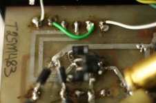
(4.65 v on secundairy ) 58.6v in the primary
measuring 2de output tr.
4.65 in sec 59.6 on primary.....1v difference
measuring 2de output tr.
4.65 in sec 59.6 on primary.....1v difference
Attachments
Last edited:
How about changing to a choke (or small cap, then choke) input power supply?
a choke might be good for later .....first need trafo' s built so have the appriate voltage for right Anode voltage of all El84
(These mono's run on 430vdc..)
Last edited:
Choke input results in a much lower HT than cap input.
Possibly it is all you need to lower the voltage (without heat and keeping the existing power tranny).
A possible reason for the high HT could be that it was originally intended to use a valve rectifier and somebody changed that to ss.
I've seen it with a Vox AC30: the GZ34 was replaced with ss diodes and the 5V heater winding was feeding a voltage doubler to raise the HT even higher. Amazingly the EL84s were still working.

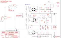
A Manley PPP EL84 + ECC81 amp. That could be the Stingray. Or the mono block version MahiCathode resistors are 10ohm paralled with a 100uf elco
An externally hosted image should be here but it was not working when we last tested it.
You measured the winding ratio 1:12,8 resulting in an impedance ratio of 1:164,3 what translates for a 8 ohm speaker in a 1K3 load. That's low. How many EL84s has the amp?
The high supply voltage might be a sign the tubes are not biassed correctly because of some reason. That can be misbalance of tubes, worn out tubes, missing negative supply or a combination.
Last edited:
So, what do you want? In my opinion you should try to resurrect the beast. For repair you have to investigate voltages at all electrodes and compare tubes with each other, to expel the possibility of loose solder contacts or tube oscillation. With voltages we have a starting point.
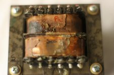
yes new trafo needed
voltages on the old trafo were to my best knowledge
See pics
Pin:
1: 155v
6: 175v
combined they feed the 4 diodes > to 'cause' the 430V Anode of the 4 El84
after elco's
2: 60v/58v
5: 60v/58v both linked
3: 13v
4: 13v both to heather of EL84 and Ecc81
voltages on the old trafo were to my best knowledge
See pics
Pin:
1: 155v
6: 175v
combined they feed the 4 diodes > to 'cause' the 430V Anode of the 4 El84
after elco's
2: 60v/58v
5: 60v/58v both linked
3: 13v
4: 13v both to heather of EL84 and Ecc81
To lower the anode voltage can i lower the pin 1 and 6 from 330 to 230v.....?
and raise the voltage of the Bias from 13v to 20-24 v ..?
and raise the voltage of the Bias from 13v to 20-24 v ..?
Attachments


Last edited:
If :
pin 1 and 6 both 115 v
4x 0,35mA EL84 = 140mA
2x 15mA ECC81 30mA
total 170 mA
pin 3 and 4 negative bias
20-24v at 20mA..?
Pin2 and 5 green wire connected 60v.....?
mA ......?
Seems right or...?
pin 1 and 6 both 115 v
4x 0,35mA EL84 = 140mA
2x 15mA ECC81 30mA
total 170 mA
pin 3 and 4 negative bias
20-24v at 20mA..?
Pin2 and 5 green wire connected 60v.....?
mA ......?
Seems right or...?
Pin 1 and 6
330v now gives 430 anode voltage
so to 230v to reach anode voltage EL84
Pin 3 & 4
to 24 v and have 2 schottkey rectifier there instead of 4x 1n4007
330v now gives 430 anode voltage
so to 230v to reach anode voltage EL84
Pin 3 & 4
to 24 v and have 2 schottkey rectifier there instead of 4x 1n4007
Is that Stingray amp really using a +420V plate supply for fixed bias EL84's? I'd think that would melt standard Russian 6P14P tubes.
Perhaps the JJ EL84 can work with that high a B+ and yield a reasonable service life.
I'd rather reduce the B+ to 325V or so, and have a wider variety of EL84 type tubes to choose from.
ECC81 = 12AT7. 15mA plate current would put it way over max plate dissipation. Are you sure it's supposed to take 12AT7?
35mA each EL84 at 320V plate-cathode looks exactly right.
--
Perhaps the JJ EL84 can work with that high a B+ and yield a reasonable service life.
I'd rather reduce the B+ to 325V or so, and have a wider variety of EL84 type tubes to choose from.
4x 0,35mA EL84 = 140mA
2x 15mA ECC81 30mA
total 170 mA
ECC81 = 12AT7. 15mA plate current would put it way over max plate dissipation. Are you sure it's supposed to take 12AT7?
35mA each EL84 at 320V plate-cathode looks exactly right.
--
Last edited:
Half 12AT7 looks like it's pulling 500uA.
The follower half is pulling 3.7mA.
The LTP is also pulling 3.7mA.
Total current per channel is 147.3mA.
The easiest method is to add a resistor between the parallel input capacitors after the bridge rectifier. You would also have to add two more balancer resistors to the series caps. So three resistors per channel. A 670 ohm resistor should drop close to 100v.
I will add a schematic of my proposal. Since this amp is biased pretty hot maybe the tubes don't go into cutoff giving mostly class A operation, the extra resistance in the power supply might not be even noticeable.
Why are you guys calculating the current draw based on the idle current (assuming that it is correct in the first place)? Consider that the peak current of class AB1 is significantly higher than the idle current, you can't size up the PT properly this way. Also what does it mean that the amp is kinda like the Stingray, is it an exact clone (or not)?
I am just going by the Stingray schematic because from what he is posting the voltage and such look very close.
Attachments
Last edited:
So, the only thing wrong is the temperature. The obvious is to add cooling because it's a proven design (?)
Max, if you want to build your own design you have to study. One thing that's not clear to me is the OPT impedance. That can't be 1K3. You probably measured CT to UL.
Max, if you want to build your own design you have to study. One thing that's not clear to me is the OPT impedance. That can't be 1K3. You probably measured CT to UL.
Sorry 25mA per tube is 107mA per channel.
The 670R should still work, if not increase to 820 or 1K. Shoot for the same bias of 250mV which is 25mA per tube, Va=330. We don't know the actual load impedance so maybe it is designed to run so hot.
I would still lower things to normal values so you can use a lot more valves and they will be a lot happier and last longer. And run a lot cooler of course.
- Status
- Not open for further replies.
- Home
- Amplifiers
- Tubes / Valves
- EL84 in triode