So i decided to build an EL34 triode mode push pull amplifier because of the better damping factor mostly and because i have a lot of EL34's compared to other tubes.
A generic case is being built by a friend as we speak and there's no strict selection of sockets/tubes to be used...
Since there's definitely people here who did this before i was wondering would anyone recommend a particular schematic, preferably not involving ECC82/12AU7 because i don't have any of those. I do have several ECC83/12AX7 and 6N1P and ECC88's. I tried simulating several of my own designs using the model for a 1650 Hammond tranny 5Kp-p to 8 ohm. However John Broskie's amplifier simulated seems to ace my designs in terms of distortion up to clipping. But that one uses only 12AU7 so it's a no-go...
I'd probably use a topology like a Williamson circuit- ECC83 input and cathodyne, ECC88 driver. They won't be drop-ins for the original circuit, you'll have to alter a lot of the component values, but you can achieve very low distortion.
Compared to the other components, a small signal triode like ECC82 is pretty cheap.
Compared to the other components, a small signal triode like ECC82 is pretty cheap.

John Broskie's amplifier simulated seems to ace my designs
Which design are you referring to? He does have over 300 blog posts! It can probably be altered to fit the valves you have.
I would stay away from the Williamson, due to its poor stability with anything but the best output transformer. A standard Mullard topology seems most sensible (gainstage DC coupled to LTP). ECC88s should have no trouble driving triode EL34s (I used ECC81 / 12AT7s last time I made a triode EL34 amp).
Thanks for the reply!
I was referring to this one.
http://www.tubecad.com/2010/03/21/push-pull power amp example for ps-4.png
It surprises me that with so cold bias as he uses, still obtains close to the typical 19W.
He did use ECC83 for the first stage and phase splitter when making the actual amp but there's no schematic. There's a quirk in the simulation where if i direct couple the split load stage to the first stage, one output will always have more distortion than the other but i think that may be an error and not actually in a real amplifier.
As for transformer stability, trust me, the ones i happened to buy so far from an enthusiast more skilled than me, take quite a bit of *intentional* destabilizing to cause oscillations.
I would stay away from the Williamson, due to its poor stability with anything but the best output transformer...
As far as I understand the stability problems with Williamson is not due to topology but due to too high GNFB together with non optimum output transformers.
When less than 20 dB GNFB is used (with skilled overall design), no stability problems exist.
Power is determined mainly by supply voltage and load impedance, not bias. The bias determines the operating class, which appears to be cool class AB in his example.Thanks for the reply!
I was referring to this one.
http://www.tubecad.com/2010/03/21/push-pull power amp example for ps-4.png
It surprises me that with so cold bias as he uses, still obtains close to the typical 19W.
I have used 6F12P in this simple configuration with many different output tubes and it really works.
https://www.dropbox.com/s/7qujsohq1ykrjlu/EL34_triode_6F12P.gif?dl=0
An externally hosted image should be here but it was not working when we last tested it.
https://www.dropbox.com/s/7qujsohq1ykrjlu/EL34_triode_6F12P.gif?dl=0
I thought the operating class was defined by both bias point and load impedance... and in turn power obtainable is determined by operating class and load impedance...
I know power is not directly determined by bias point, but by how much distortion will be produced and how objectionable it is. Triodes distort quite "gracefully" as some describe and in p-p will have mostly 3rd harmonic distortion and maybe a tiny bit of 2nd if there's some imbalance (and there's always some imbalance). But if you lower the bias enough, the 5th order harmonics start to poke their head out just a little. But still that may not be so bad because triodes don't really produce higher orders until they clip hard.
Now back on track, i'll do my first test 3-4 days from now when the casing arrives, and i'll use what i have from my previous amp which was EL84 p-p. The transformers are 8K to 8 ohm no screen taps, rated for 20W. They can probably take even more than 20W, because at 12W the linear response was from 10Hz to 30KHz with the tubes in pentode mode (they were EL84 as i said). The speakers are no longer 8 ohm since i changed to a respectable speaker cables so now are 6 ohm. So the primary transformer impedance the EL34's will see will be more like 6K. Still not the 5K recommended for triode mode but will play some music nevertheless. I will not obtain the 19W claimed but at lower power i'll have lower distortion figures with higher Raa, and unfortunately overall even lower plate efficiency than the already low one of triode mode. But that's ok i don't aim for infinite power but fidelity.
Edit: Thanks a great deal for the schematic! I myself had come up with an ECC83 gain + ECC88 pi, but the overall gain was rather low. I think i'll do something similar to what you did with an EF86 for gain & ECC88 for PI. But i'll look up this tube of yours maybe i have an equivalent.
Last edited:
Class is indeed finally determined by the choice of HT, load and bias. But you usually have the HT and load nailed down more than the bias, which is more of a flexible thing. You can mess with the bias (class) without significantly altering the output power.I thought the operating class was defined by both bias point and load impedance...
and in turn power obtainable is determined by operating class and load impedance...
There is some inevitable interplay between the three, more so with triodes than pentodes, but as a first (and pretty good) approximation only supply voltage and load determine power. Once those are set, the bias remains only to set the class of operation.
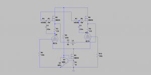
That's precisely my point, everything's more or less interconnected in pretty much everything, let alone in amplifiers. Anyway, thanks for the insight and let me introduce you folks to my concoption. Feel free to slam it if you think it's lousy. The 47 ohm resistor in the first stage is a provision for adding feedback but that can be accurately done only when the amp is complete (and if i feel it's needed). I'm not sure i'm comfortable with fixed bias these tubes being already worn & everything but in my previous experiences fixed bias offered me the most crisp clear sound. Besides i will fit each plate+screen pair with a 100mA slow blow fuse, or 150mA fast blow. That's cause i don't want them to blow at signal peaks but to blow when there's a thermal runaway.
An externally hosted image should be here but it was not working when we last tested it.
Looks fine. You don't really need C5, and most people will jump at the chance to eliminate a capacitor!
Well, there wasn't any noticeable difference with or without it so i guess i'll remove it. I don't like electros either and always try to thinner their numbers.
n my previous experiences fixed bias offered me the most crisp clear sound.
Have you tried CCS tails?
In balanced circuits, my experience is, the better the balance, the better the sound in every way. In practice this means forced CCS balance.
This also makes the OTs job just a little bit easier. For best sound, in balanced circuits also, always go parafeed for further improvement.
In a balanced circuit you can go "directly coupled" parafeed to eliminate the parafeed cap (OT from anode to anode but center tap not connected to B+, gyrator loads provide B+ to tube plates).
But anyway, have you tried CCS forced balance?
Also, if you make your circuit clean enough, there's no need to have 12AX7 level gain at all - I'd go full balanced with ECC88 in a long (CCS) tailed pair. Best to have no need for feedback than to plaster over problems with it.
You meant CCS tail for the output stage? That sounds interesting, however it presents the problem of bias imbalance if the tubes are not (and they will not be) identical. But i could use one CCS for each cathode, and couple them together at AC only via capacitors. But using CCS for the output tubes leaves only the most inefficient class A that also kills the tubes in a not so long time.
Parafeed is most interesting, much like the topology of an average SS amp driving a transformer to adapt impedance. But i don't have a transformer suitable, i only have PP transformers, which would not work parafeed.
And feedback is not at all about the cleanness, i actually love it when tubes distort just a tiny bit, it sounds extremely "agressive" to my ear and gives a spatial perception (for some tubes), but it's about output impedance. That's also why i opted for triode mode instead of pentode. Both would have been just as simple to implement. But my experience with pentode amps was not entirely joyful. Even with FB they can't damp my speakers properly. Now, triodes if biased hot enough need no FB but i'd rather not sacrifice the tube life just to not use a little bit of FB. And keep in mind these are old used tubes that will run fixed bias. Running them hot is almost certain to get them into runaway.
Yes i used CCS in the tail of a phase splitter, which made it better by a little bit not sure if perceptible to the ear or not... I used an ECC88 triode as CCS. A pentode would supposedly be much better but i don't want to waste those on a CCS. If i'm gonna use a pentode it will be in the schematic posted on the other page. Although i'll probably bias my 34's a bit cooler than that.
Last edited:
You meant CCS tail for the output stage? That sounds interesting, however it presents the problem of bias imbalance if the tubes are not (and they will not be) identical.
Yes. Why is bias imbalance a problem? What matters is the balance of the output signal - bias imbalance only (unless the tubes are grossly dissimilar) very very slightly lowers available peak output power.
CCS tails are used to make tube matching unnecessary. That it indeed does.
But i could use one CCS for each cathode, and couple them together at AC only via capacitors.
Why?
But using CCS for the output tubes leaves only the most inefficient class A that also kills the tubes in a not so long time.
If power efficiency is of great importance, you shouldn't use class A circuits. However 99% of people don't really need as much power as they think they do. Have you ever tried a 2W amplifier? Was it not loud enough? 5W is usually just showing off (unless you own peculiar speakers).
As a rule, people don't use tubes for power efficiency.
Parafeed is most interesting, much like the topology of an average SS amp driving a transformer to adapt impedance. But i don't have a transformer suitable, i only have PP transformers, which would not work parafeed.
PP OT is just fine. As a matter of fact, the ability to use PP OTs with no air gap in a SE circuit is one of the main selling points of the parafeed topology.
In any circuit, parafeed makes the OT act and sound like a much more expensive OT.
I always use cheap and small PP OTs in parafeed circuits. They sound very transparent compared to serial feed mode.
And feedback is not at all about the cleanness, i actually love it when tubes distort just a tiny bit, it sounds extremely "agressive" to my ear and gives a spatial perception (for some tubes), but it's about output impedance.
EL34 in triode mode will have a bit of harmonics when driven hard. That's a feature. For high fidelity, I would choose a tube that is sufficiently linear without any NFB.
As per output impedance; use gyrator plate loads for the EL34s and put the OT in parafeed (with a cap in series) or in 'pseudo parafeed' (without the cap) between the MOSFET sources, and you will have excellent damping factor without resorting to NFB. Your current OT is completely suitable for this. Such a low impedance driving source for the OT will control the load in a very efficient manner without sacrificing any fidelity.
And keep in mind these are old used tubes that will run fixed bias. Running them hot is almost certain to get them into runaway.
Use a CCS tail for them. Then runaway is literally completely impossible; this in addition to sonic benefits of complete forced balance.
In schematic posted below the tubes are biased at around 35mA per tube, with about 180V across them. (Apply 220V control voltage to junction of R4 & R7.)
This gives about 6W of dissipation - the EL34 g2 alone would take this. At 6W the tubes will run pretty much forever, heater allowing.
With CCS tails you are free from runaways, and you can control the tube dissipation by adjusting the current.
ECC88 triode as a CCS will not force balance, it will just nudge towards it.
Attached my suggestion for a balanced EL34 power stage. L1 is OT primary (around 10k impedance ok, if less, use a bigger cap, or no cap at all). MOSFETs can be IRF820 for example.
If you put the ECC88 in front of this, as a CCS tailed pair like this, you will have no need for NFB for linearity (if you like the small amount of H3 the EL34 makes) or output impedance.
Attachments
That's precisely my point, everything's more or less interconnected in pretty much everything, let alone in amplifiers. Anyway, thanks for the insight and let me introduce you folks to my concoption. Feel free to slam it if you think it's lousy. The 47 ohm resistor in the first stage is a provision for adding feedback but that can be accurately done only when the amp is complete (and if i feel it's needed). I'm not sure i'm comfortable with fixed bias these tubes being already worn & everything but in my previous experiences fixed bias offered me the most crisp clear sound. Besides i will fit each plate+screen pair with a 100mA slow blow fuse, or 150mA fast blow. That's cause i don't want them to blow at signal peaks but to blow when there's a thermal runaway.
An externally hosted image should be here but it was not working when we last tested it.
This looks like 90% of my most recent project. You can easily eliminate C1 too, and DC couple the ECC83 to the ECC88 splitter, making feedback much easier to apply.
For the precise reason you mentioned: to gain the benefit of forced matching but add to that forced equal biasing.Quote:
But i could use one CCS for each cathode, and couple them together at AC only via capacitors.
Why?
If power efficiency is of great importance, you shouldn't use class A circuits. However 99% of people don't really need as much power as they think they do. Have you ever tried a 2W amplifier? Was it not loud enough? 5W is usually just showing off (unless you own peculiar speakers).
As a rule, people don't use tubes for power efficiency.
I know and completely agree, if efficiency is a thing i'd build another hybrid but then i already have one. Back when tubes were "the only thing" in amplification people would obviously aim to maximize output power for given power consumption. I was curious how one of those "classic" "spirit of the era" amps would sound, as opposed to class A amp. Clearly a class A amp would ace any of the conventional designs in terms of fidelity. I haven't made my mind up yet but i'll test and compare with my ears to decide which is best.
Your current OT is completely suitable for this.
That makes me a bit confused since what you used in your (very interesting) schematic is quite different. Mine is a push pull transformer. So if i connect it like in your design there might be almost no output because it would get cancelled. But i could connect the center tap to ground and the sides to each plate by capacitors... not sure if it would work in the same way but maybe...
Those loads i have plenty of, better yet i can even use IRF840 which is even more sturdy. got plenty of those.
...You can easily eliminate C1 too, and DC couple the ECC83 to the ECC88 splitter...
This is recommended only when relatively low driving voltage for output tubes is required. Just as pentode connected EL84 etc.
Optimum anode voltage of 12AX7 is not same as optimum grid voltage of the 6DJ8 cathodyne.
AC-coupling makes possible to bias both stages to most linear operating point.
DC-coupling is allways a compromise.
- Status
- Not open for further replies.
- Home
- Amplifiers
- Tubes / Valves
- EL34 Triode strapped amplifier