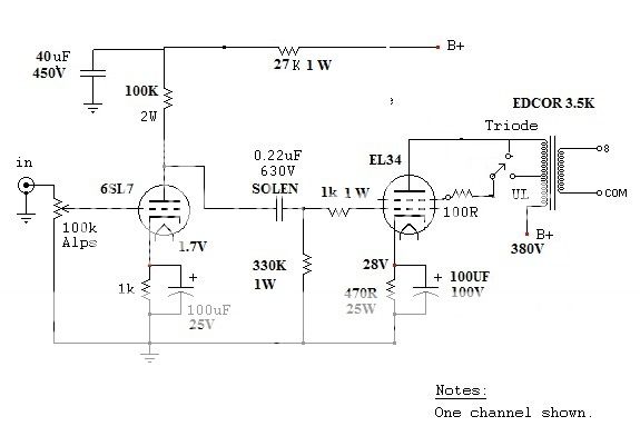
Hi guys, what do you think of the circuit? Does the power tube cathode resistor 880k is too high. The bias amp is at 32ma if based on 28v. Thanks for reply.
Last edited:
Ok. Noted with thanks. What about triode and UL connections. Any issue??You need 390 Ohms to 470 Ohms for proper operating point (Ik~60-70mA).
That means I have 2x100 ohms resistor? Any illustration? Thank you.100 Ohms resistor solder directly to screen (G2; pin 4 at socket).
ok I guess I know what you mean. So connect 100ohm to screen. Both UL and triode mode will have 100 ohms connected to screen when you switch to either one.No two resistors, only one, but directly solder to screen!
Hi guys, what do you think of the circuit? Does the power tube cathode resistor 880k is too high. The bias amp is at 32ma if based on 28v. Thanks for reply.
I have a 330R 10w in place doesn't get hot why 25w and 220uf 35v??
Well, I also think 10W is good enough.I have a 330R 10w in place doesn't get hot why 25w and 220uf 35v??
Well, I also think 10W is good enough.
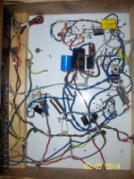
ok built the amp from schematics and do not like the sound I did replace the 6SL7 with 6SN7 may have made the sound better if I used 6SL7 but not alot of gain very flat. I think I would go for a better schematics then this but only my opinion
Attachments
...do not like the sound I did replace the 6SL7 with 6SN7 may have made the sound better...
The non-linearities (=distortion) are created at the output stage, not at the voltage amplifying stage 6SL7.
Therefore it is obvious that changing 6SL7 to 6SN7 is not a solution.
That circuit can be improved a lot by applying negative feedback from the speaker output to the cathode of 6SL7.
At the same time frequency response, damping factor and signal to hum ratio is improved.
Last edited:
The non-linearities (=distortion) are created at the output stage, not at the voltage amplifying stage 6SL7.
Therefore it is obvious that changing 6SL7 to 6SN7 is not a solution.
That circuit can be improved a lot by applying negative feedback from the speaker output to the cathode of 6SL7.
At the same time frequency response, damping factor and signal to hum ratio is improved.
I will try the feedback to see if that changes the sound, I have brand new 6SN7 coming so I will try new ones to see if the old 6SN7 I have are no good too old. I have 6N9P that it is said a straight replacement for 6SL7 and I tried as well and got a higher gain but a bit of distortion at high volume.
Below is an example where some 6 dB of GNFB is added to triode connected output stage.
So you only need to add resistors R14 and R11 to your existing circuit.
This will halve the THD.
So you only need to add resistors R14 and R11 to your existing circuit.
This will halve the THD.
An externally hosted image should be here but it was not working when we last tested it.
Member
Joined 2009
Paid Member
I'm not expert enough to say what should change, but it seems to me that for a single ended amplifier of this topology the last thing that should be needed is global feedback. It should be possible for it to sound very good without. The UL operation should be fine.
I am wondering if the speakers are sensitive enough or are difficult to driver and are forcing the amplifier to be operated where distortion is high ?
I would re-visit the operating points, and even the wiring as I've read there are effects simply from which way around you connect up to the OPT primary due to winding capacitances etc. - and perhaps even more so with UL because the % of feedback depends which way it is wired.
I am wondering if the speakers are sensitive enough or are difficult to driver and are forcing the amplifier to be operated where distortion is high ?
It is exactly negative feedback that improves the ability of the amplifier to feed difficult loads.
Anyhow, it is waisting of time to speak about good sound because it is depending on the listener to another.
There is no such unambiguous concept as good sound. I have clearly observed this with listening test made by different persons but with the same equipment. The results are not consistent at all.
Last edited:
It is exactly negative feedback that improves the ability of the amplifier to feed difficult loads.
Anyhow, it is waisting of time to speak about good sound because it is depending on the listener to another.
There is no such unambiguous concept as good sound. I have clearly observed this with listening test made by different persons but with the same equipment. The results are not consistent at all.
I will try the things you say to do today and then I will build this one as I have 6SJ7 Metal valves as well and see which one is better I'm liking the schematic of the 6SJ7 as I like the sound I will change the 100R on the output tube on pin 4 to 1k and wire it to pin 3 and the input volume will be 100k A pot
Attachments
I will try the things you say to do today and then I will build this one as I have 6SJ7 Metal valves as well and see which one is better I'm liking the schematic of the 6SJ7 as I like the sound I will change the 100R on the output tube on pin 4 to 1k and wire it to pin 3 and the input volume will be 100k A pot
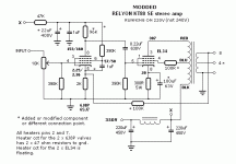
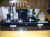
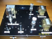
Ok built the amp from schematics above had to mod a few parts so I could use 6N3C as well as I can use EL34 power tubes seems to have a good sound, I got rid of feedback didn't make any difference I tried the 6SL7 EL34 from schematics on page 1 but just didn't like the output was low and damp. I hope others have better luck them me on the 6SL7!! 🙂
Attachments
I will try the things you say to do today and then I will build this one as I have 6SJ7 Metal valves as well and see which one is better I'm liking the schematic of the 6SJ7 as I like the sound I will change the 100R on the output tube on pin 4 to 1k and wire it to pin 3 and the input volume will be 100k A pot
hello ,
the potentiometer is very slow ! 10 K , not use 47 K or 100 K ?
and not grid stop to G1 in EL 34 ?
😉
- Status
- Not open for further replies.
- Home
- Amplifiers
- Tubes / Valves
- EL34 SE ultralinear schematic