6J1/6AK5 can use pentode or triod by SW1,I dont know do it have good for sound?
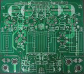
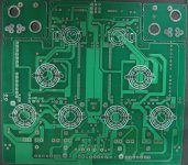
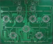
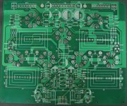
There are power supply and PCB for 2 chanel L+R+power supply
There are power supply and PCB for 2 chanel L+R+power supply
Last edited:

Mullard 5-20. One of the classics. Your phase splitter will be unbalanced, though. A CCS for the tail will fix that, otherwise you need to unbalance the plate resistors a bit (if memory serves, 28k and 33k, but I'd double-check that).
Mullard 5-20. One of the classics. Your phase splitter will be unbalanced, though. A CCS for the tail will fix that, otherwise you need to unbalance the plate resistors a bit (if memory serves, 28k and 33k, but I'd double-check that).
Thank mod.
That a good idea.
I not perfect my design, a VR adjust the balance current anode 6SN7,if dont so I must macthpair 6SN7
Last edited:
You are using a pentode gain stage and a triode phase splitter, which is a lot of gain.
But you also are using pure pentod eoutput stage, and none of it with any loop negative feedback..
1/ I suspect you will have HUGE gain, far tooo much for any normal system
2/ You will have VERY high output impedance, which will not be good for 90% of speakers.
Regards, Allen
But you also are using pure pentod eoutput stage, and none of it with any loop negative feedback..
1/ I suspect you will have HUGE gain, far tooo much for any normal system
2/ You will have VERY high output impedance, which will not be good for 90% of speakers.
Regards, Allen
You are using a pentode gain stage and a triode phase splitter, which is a lot of gain.
But you also are using pure pentod eoutput stage, and none of it with any loop negative feedback..
1/ I suspect you will have HUGE gain, far tooo much for any normal system
2/ You will have VERY high output impedance, which will not be good for 90% of speakers.
Regards, Allen
Thank Allen.
I have using feedback by gain too much.
Can you see it ? R21 = 1.8K, R22 = 100 ohm.
Attachments
Check the screen grid resistors for the EL34 p-p. I read 1R; should read 400-1K ?
My charts give conflicting results; some mention common 800R-1K resistor and fixed bias supply. Other members could add.
richy
R for G2 can choice other values.
I am option for Ultralinear, not use R for G2.
Thank richwalters.
OK, I can see the NFB resistors now I am shown.
I personally like all connections shown in an amp schematic, at least for the signal path, otherwise you can't get a conceptual understanding of it with a look, but have to hunt around findinding things marked FBR etc. Not intuitive.
Regards, Allen
I personally like all connections shown in an amp schematic, at least for the signal path, otherwise you can't get a conceptual understanding of it with a look, but have to hunt around findinding things marked FBR etc. Not intuitive.
Regards, Allen
OK, I can see the NFB resistors now I am shown.
I personally like all connections shown in an amp schematic, at least for the signal path, otherwise you can't get a conceptual understanding of it with a look, but have to hunt around findinding things marked FBR etc. Not intuitive.
Regards, Allen
OK.
Sorry Allen,I am not notice 😀
- Status
- Not open for further replies.
- Home
- Amplifiers
- Tubes / Valves
- EL34 PP New Design of newbie